
Precise time measuring method

A measurement method and technology of precise time, which can be used in electrical unknown time interval measurement, phase measurement, and time interval measurement devices, etc., and can solve problems such as fractional square wave width errors.

Inactive Publication Date: 2011-05-18
BEIHANG UNIV
View PDF0 Cites 0 Cited by
  • Summary
  • Abstract
  • Description
  • Claims
  • Application Information

AI Technical Summary

Problems solved by technology

In the usual measurement methods, due to the characteristics of the square wave waveform, it is generally only accurate to an integer number of square waves, and an error of fractional times the width of the square wave is introduced.

Method used


Image

  • Precise time measuring method
  • Precise time measuring method
  • Precise time measuring method

Examples


Embodiment Construction

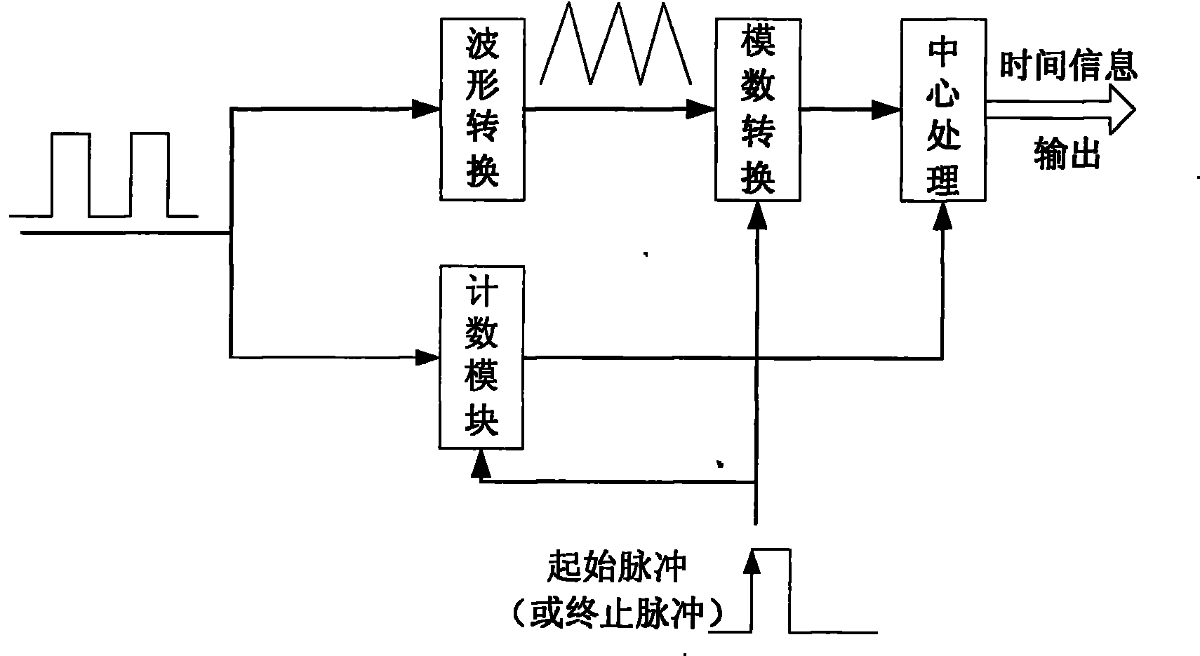
[0010] The present invention is described in further detail below. see figure 1 , the present invention is composed of a waveform conversion module, an analog-to-digital conversion module, a counting module, and a central processing module.

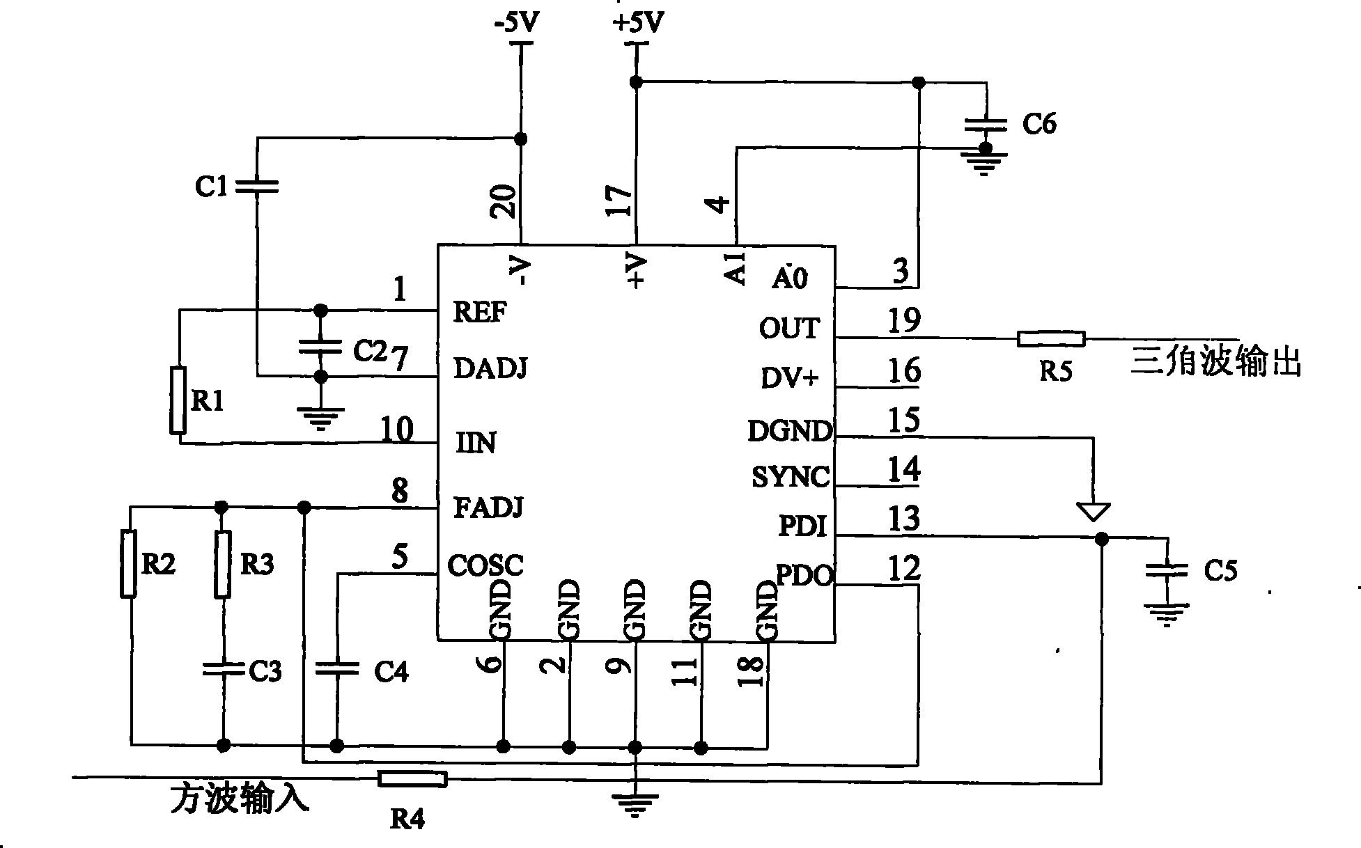
[0011] The function completed by the A waveform conversion module is to convert the square wave signal into a synchronous triangular wave signal. figure 2 A (not limited to) waveform conversion method realized by MAX038 is given.

[0012] The function completed by the B analog-to-digital conversion module is: under the action of the start pulse and the stop pulse, perform corresponding analog-to-digital conversion on the triangular wave. Among them, the conversion is required to be completed within a start or stop pulse.

[0013] The function completed by the C counting module is to count the integer times square wave period between the start pulse and the end pulse, and obtain the square wave integer times timing information.

[001...


PUM


Abstract

The invention relates to a precise time measuring method, consisting of a waveform conversion module, an analog-to-digital conversion module, a counting module and a central processing module. The invention has the advantages that a method for eliminating decimal phase error of square wave is provided, and the method effectively improves the time measuring precision with lower cost.

Description

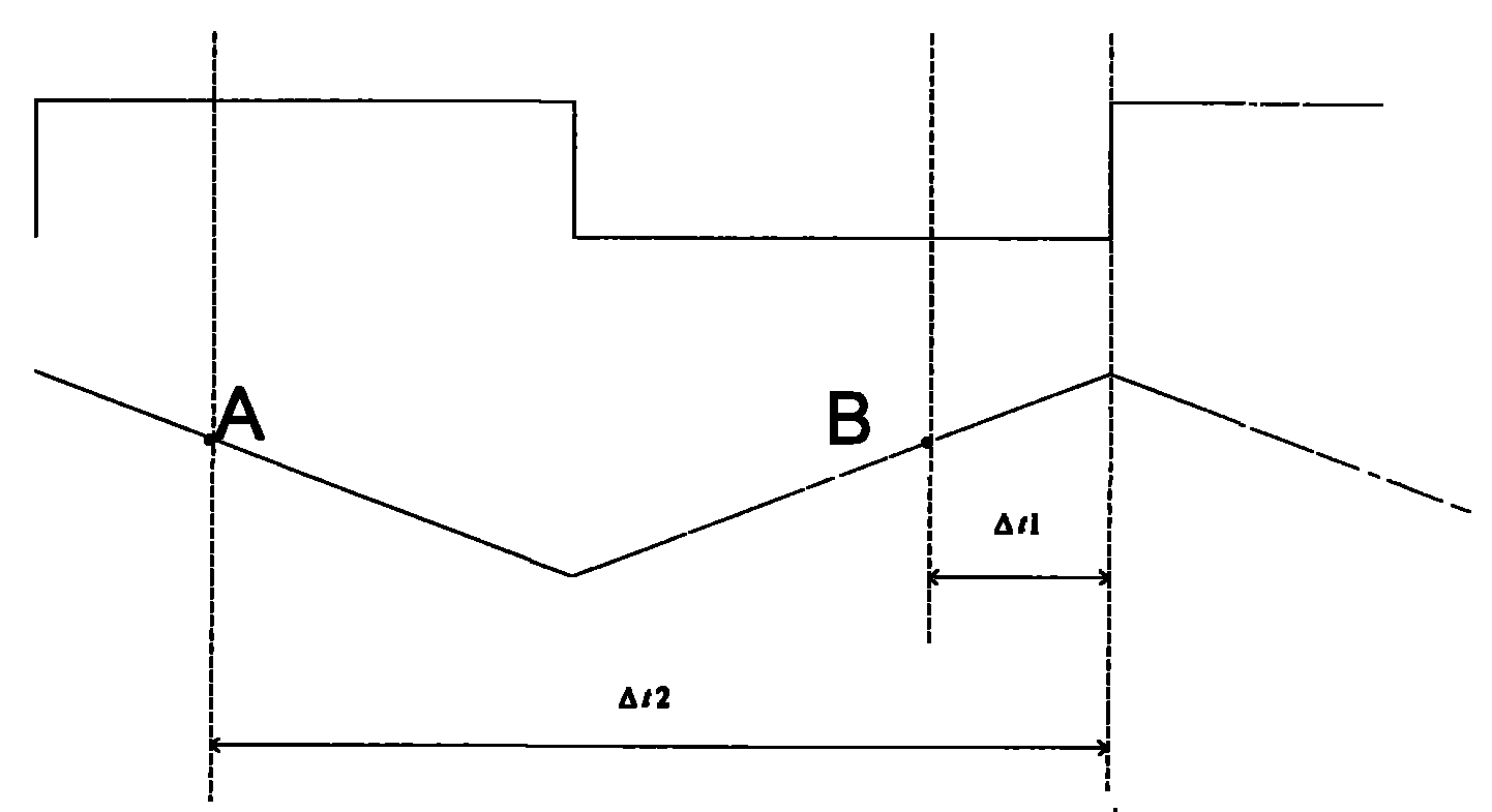
technical field [0001] The invention relates to a precise time measurement method, more specifically, a method for converting a square wave into a triangular wave by using waveform conversion, thereby performing precise time measurement. Background technique [0002] In many applications, it is necessary to obtain accurate time information. In the usual measurement methods, due to the characteristics of the square wave waveform, it is generally only accurate to an integer number of square waves, and an error of fractional times the width of the square wave is introduced. Thus, the margin of error is the width of a square wave. [0003] The precise time measurement method is an effective technical means for reducing the time measurement error. It converts the square wave into a triangle wave, and obtains the precise phase of the square wave through the measurement of the amplitude of the triangle wave, thereby obtaining precise time information. Contents of the invention ...

Claims


Application Information

Patent Timeline
Patent Type & Authority Patents(China)
IPC IPC(8): H03K5/00G04F10/06G04F10/04
Inventor 李署坚宋伟宁文霄杰孙宇明
Owner BEIHANG UNIV
Learn More