Sound wave distance measuring device

A technology of sound wave distance measurement and sound wave reception, which is applied in the field of sound wave distance measurement devices, and can solve the problems of low accuracy of sound wave distance measurement

Inactive Publication Date: 2019-06-21
林项武
View PDF0 Cites 0 Cited by
  • Summary
  • Abstract
  • Description
  • Claims
  • Application Information

AI Technical Summary

Problems solved by technology

[0004] The purpose of the present invention is to provide a high-precision acoustic wave ranging device to solve the technical problem of low accuracy of acoustic wave ranging in the prior art

Method used


Image

  • Sound wave distance measuring device
  • Sound wave distance measuring device
  • Sound wave distance measuring device

Examples


Embodiment 1

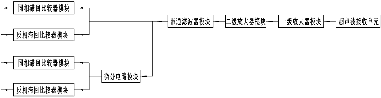
[0042] like figure 1 , for the sine or cosine signal received by the ultrasonic receiving sensor, it is first amplified by the first-level amplifier module and the second-level amplifier module, and then filtered by the band-pass filter module. The signals before and after the phase shift are sent to two groups of electrical signal-to-DC level modules, and each group of electrical signal-to-DC level modules consists of a non-inverting hysteresis comparator module and an inverting hysteresis comparator module to obtain 4 Group intermittent signal level output.

Embodiment 2

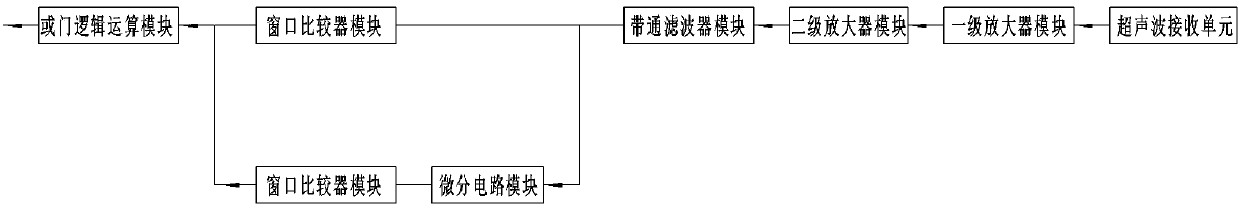
[0044] like figure 2 , for the sine or cosine signal received by the ultrasonic receiving sensor, it is first amplified by the first-level amplifier module and the second-level amplifier module, and then filtered by the band-pass filter module. The signals before and after phase shifting are respectively sent to 2 groups of electrical signal to DC level modules, and each group of electrical signal to DC level modules includes a window comparator module to obtain 2 groups of discontinuous signal levels and 2 groups of discontinuous signal levels The signals are combined by the OR gate logic operation module and then output.

Embodiment 3

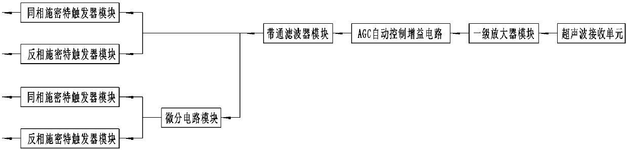
[0046] like image 3 , for the sine or cosine signal received by the ultrasonic receiving sensor, it is first amplified by the first-stage amplifier module and the AGC automatic control gain circuit module, and then filtered by the band-pass filter module, and the differential circuit module is used to shift the phase by π / 2, The signals before phase shift and after phase shift are sent to 2 sets of electrical signal to DC level modules respectively, and each set of electrical signal to DC level modules consists of 1 in-phase Schmitt trigger module and 1 inverting Schmitt trigger module , get 4 sets of intermittent signal level output.


PUM


Abstract

A sound wave distance measuring device comprises a time measurement and data processing module, a sound wave transmitting circuit, a sound wave transmitting sensor, a sound wave receiving sensor and asound wave receiving circuit. The sound wave receiving circuit comprises an amplifying circuit, also comprises a phase shift circuit and electric signal-to-direct current level circuits, the electricsignal before phase shift outputs discontinuous direct current signal level through the first electric signal-to-direct current level circuit, the phase shift circuit changes a phase electric signal,the electric signal subjected to phase position change through the phase shift circuit outputs discontinuous direct current signal level through the second electric signal-to-direct current level circuit, the two paths of discontinuous direct current levels are combined and then are output to the time measurement and data processing module, to realize distance measuring. The sound wave distance measuring device has the technical effects that by adopting the combination of the phase shift circuit and the periodically changed electric signal-to-direct current level circuits, the periodically changed electric signals before and after phase shift are respectively converted into discontinuous direct current signal levels, combined and output or respectively output, so that the input sine can be converted into the direct current signal levels.

Description

technical field [0001] The invention relates to a sound wave distance measuring device. Background technique [0002] Using the time-of-flight method for distance measurement, the existing problem is that the sine or cosine wave electrical signal is obtained after the sound wave is received by the sensor, and only discontinuous signal levels can be obtained through the amplification and comparison circuit, and the length of the signal level interval determines the length of the transition. The accuracy of time measurement will affect the distance measurement accuracy. [0003] Moreover, the measurement of sound velocity is usually calculated by formulas including parameters such as temperature and air pressure, and there are certain errors, which further reduces the accuracy of sound wave distance measurement. Contents of the invention [0004] The object of the present invention is to provide a high-precision acoustic wave ranging device to solve the technical problem of...

Claims


Application Information

Patent Timeline
Patent Type & Authority Applications(China)
IPC IPC(8): G01S15/08G01S7/527
Inventor 林项武
Owner 林项武
Why Eureka
Try Eureka