
Intelligent monitoring air switch

An air switch and intelligent monitoring technology, which is applied to the protection switch, the parts of the protection switch, and the status indication of the switch equipment, etc., can solve the problems of changing the switch state of the handle, the inability to directly judge the switch state of the handle, and the uncertain temperature of the cable. To achieve the effect of accurate detection results

Pending Publication Date: 2019-07-23
苏州鳗鱼电气有限公司
View PDF0 Cites 2 Cited by
  • Summary
  • Abstract
  • Description
  • Claims
  • Application Information

AI Technical Summary

Problems solved by technology

[0004] 1. The temperature of the cables at the two terminals is uncertain. Currently, a cable temperature measuring device is installed on the outside of the terminals, but the temperature detection value of the terminals measured outside the air switch is not accurate enough, and additional equipment will occupy additional space;
[0005] 2. It is impossible to directly judge the switch status of the handle, but only by whether the load is working or not. If the load fails, it will cause a wrong judgment;
[0006] 3. When the circuit fails, the air switch is automatically disconnected, and people cannot judge whether the circuit is overloaded or short-circuited, so corresponding measures cannot be taken, and circuit faults cannot be eliminated and repaired in real time;
[0007] 4. The existing air switch handle is exposed to the outside, and the handle may be affected by external interference (such as children's touch or object impact) to change the switch state. For places that require continuous power supply, the existing structure may have the possibility of accidentally touching the switch;
[0008] 5. The existing air switch only has the function of opening and closing the circuit, and the magnitude of the circuit current cannot be determined

Method used


Image

  • Intelligent monitoring air switch
  • Intelligent monitoring air switch
  • Intelligent monitoring air switch

Examples


Embodiment Construction

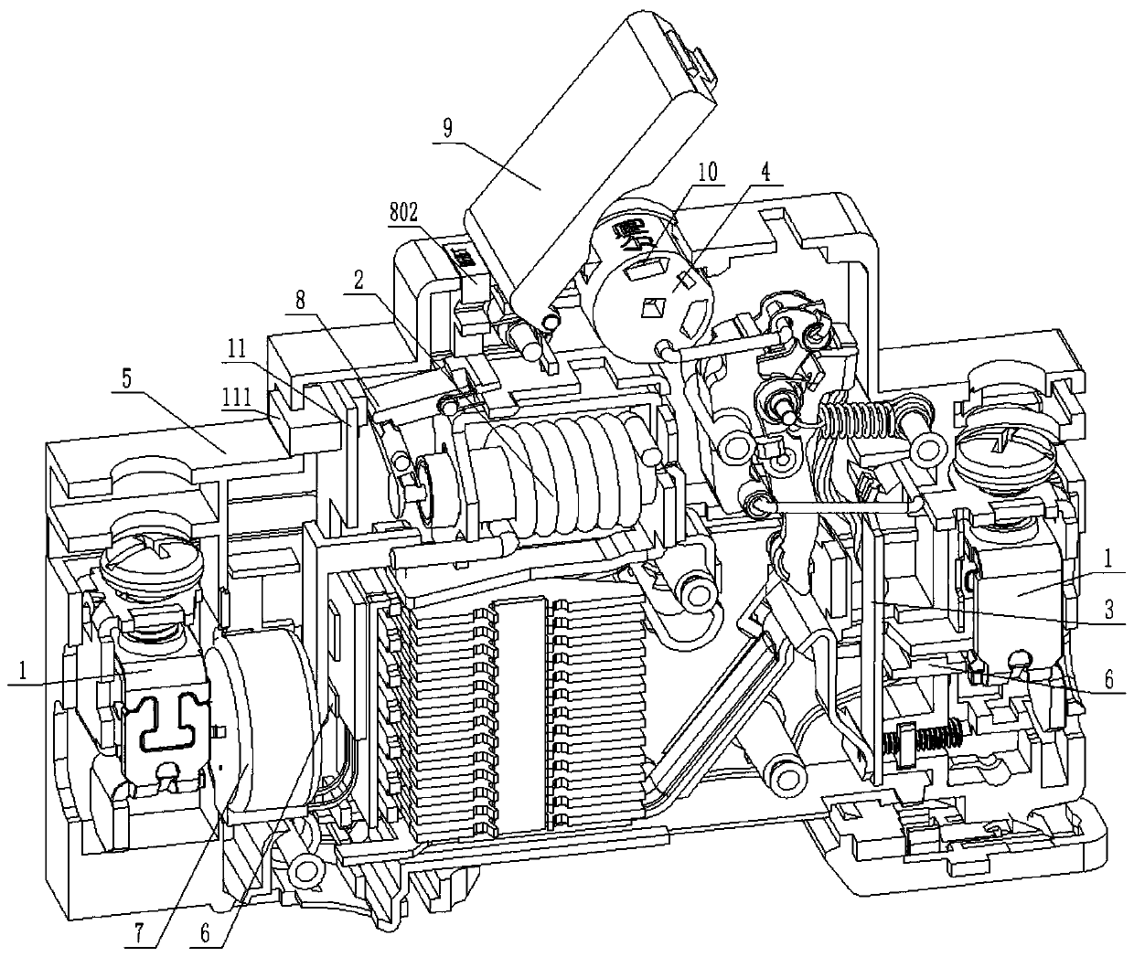
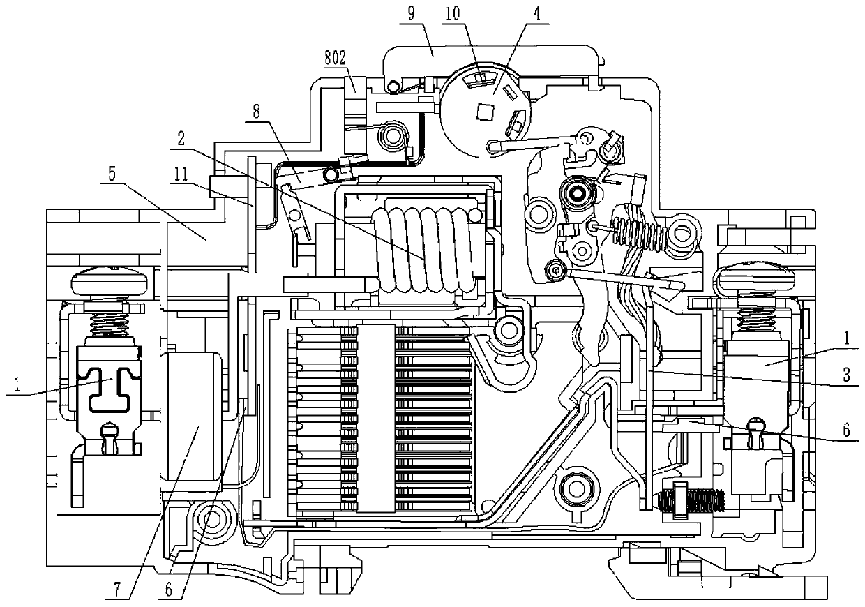
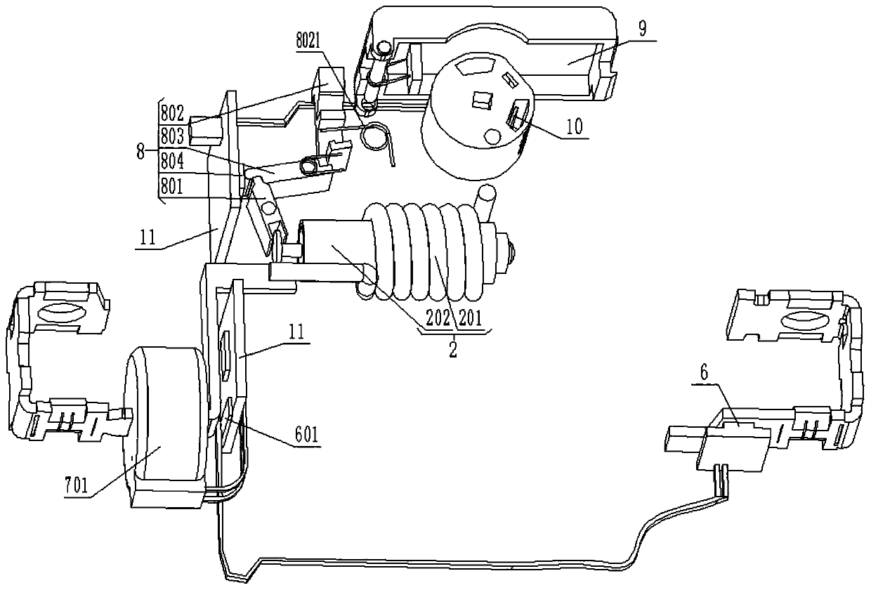
[0041] The present invention is specifically described below in conjunction with accompanying drawing, as Figure 1-15 As shown, an intelligent monitoring air switch includes a terminal 1 connected to an external cable, an electromagnetic release 2 for short circuit protection, a thermal bimetal 3 for overload protection, and a closing mechanism used as a switch 4. The rapid arc extinguishing mechanism and the housing 5 that holds all the components also include: a temperature detection mechanism 6, a current sampling mechanism 7, a short circuit fault detection mechanism 8, a safety protection cover 9, a handle status display mechanism 10 and an information collection circuit plate 11.

[0042] Such as Figure 8-11 As shown, the short-circuit fault detection mechanism 8 is arranged at one end of the electromagnetic release 2 close to the housing 5 to determine whether a short circuit occurs by judging the current operating state of the electromagnetic release 2; 2 includes ...


PUM


Abstract

The invention discloses an intelligent monitoring air switch. The intelligent monitoring air switch comprises a temperature detection mechanism, a current sampling mechanism, a short circuit fault detection mechanism, a safety protection cover and a handle state display mechanism. The short circuit fault detection mechanism is arranged at the end, close to a shell, of an electromagnetic release and judges whether a short circuit occurs or not by judging the current action state of the electromagnetic release, the safety protection cover can detect whether a cover body is opened or not while protecting a handle from being touched inadvertently, and the handle state display mechanism enables the current state identification of the switch to be eye-catching through the light emission of an LED lamp. The intelligent monitoring air switch has the beneficial effects that the short circuit fault detection mechanism is arranged on one side of the electromagnetic release, when short circuit occurs, a magnetic core acts, a second connecting rod can touch a travel switch, and therefore short circuit signals are sent to external equipment through the travel switch, and workers can clearly knowthat the short circuit occurs in the circuit; and the safety protection cover is arranged outside the shell, and can be used for judging whether the circuit has an overload fault or not while the handle is protected from being touched inadvertently.

Description

technical field [0001] The invention relates to the field of air switches, in particular to an intelligent monitoring air switch. Background technique [0002] Air switch, also called air circuit breaker, is a switch that automatically disconnects when the current in the circuit exceeds the rated value. It integrates control and multiple protection functions. In addition to the basic switching circuit functions, it can also protect the load from short circuit and overload. [0003] According to the future planning of the National Energy Administration for electric power development in recent years, it is required to develop safely, intelligently and efficiently, and reform and innovate. Therefore, based on this, compared with the traditional air switch, there are deficiencies in the following aspects: [0004] 1. The temperature of the cables at the two terminals is uncertain. Currently, a cable temperature measuring device is installed on the outside of the terminals, but ...

Claims


Application Information

Patent Timeline
IPC IPC(8): H01H71/04H01H71/06H01H71/08H01H71/10H01H71/24H02H3/02H02H3/04H02H3/10G01D21/02
CPCH01H71/08H01H71/04H01H71/06H01H71/1054H01H71/24H02H3/02H02H3/042H02H3/10G01D21/02H01H2071/046
Inventor 欧阳守飞
Owner 苏州鳗鱼电气有限公司
Learn More