Circuit breaker device

A circuit breaker and motion sensor technology, which is applied to emergency protection devices, circuits, and parts of protective switches, etc., can solve the problem of lack of circuit breaker status monitoring

Pending Publication Date: 2021-11-02
杭州德睿达电气有限公司
View PDF0 Cites 0 Cited by
  • Summary
  • Abstract
  • Description
  • Claims
  • Application Information

AI Technical Summary

Problems solved by technology

[0003] Aiming at the above-mentioned deficiencies in the prior art, a circuit breaker device provided by the present invention solves the problem of lack of monitoring the state of the circuit breaker itself in the prior art

Method used


Image

  • Circuit breaker device
  • Circuit breaker device

Examples


Embodiment Construction

[0023] The specific embodiments of the present invention are described below so that those skilled in the art can understand the present invention, but it should be clear that the present invention is not limited to the scope of the specific embodiments. For those of ordinary skill in the art, as long as various changes Within the spirit and scope of the present invention defined and determined by the appended claims, these changes are obvious, and all inventions and creations using the concept of the present invention are included in the protection list.

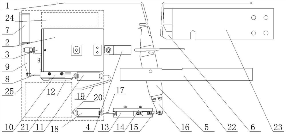
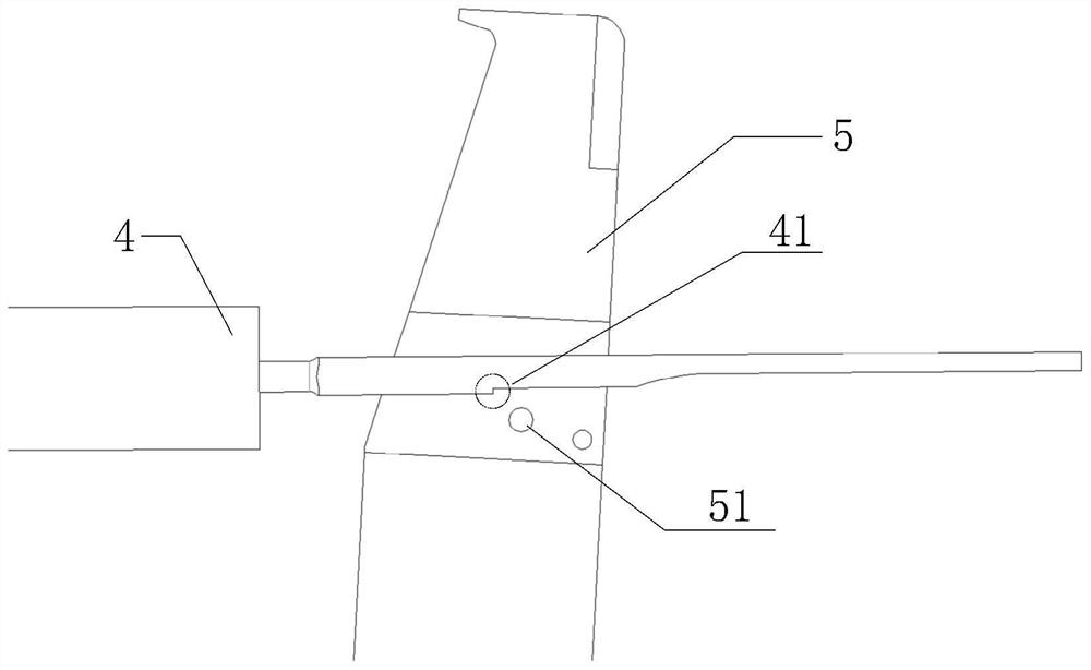
[0024] Such as figure 1 As shown, a circuit breaker device includes: an arc striker 1, a permanent magnet mechanism housing 2, a moving iron core 3, a shift fork 4, a moving contact 5, a static contact 6 and a shielding box 25;

[0025] The moving iron core 3 is fixed on one side of the permanent magnet mechanism housing 2; one end of the shift fork 4 is fixed on the other side of the permanent magnet mechanism housing 2, a...


PUM


Abstract

The invention discloses a circuit breaker device which comprises a permanent magnetic mechanism shell, a movable iron core, a shifting fork, a movable contact, a static contact, a shielding box, an optical fiber temperature sensor, a mechanism action sensor and a contact action sensor. The state of the circuit breaker is monitored through the mechanism action sensor, the contact action sensor and the optical fiber temperature sensor, and the problem that the state of the circuit breaker cannot be monitored in the prior art is solved.

Description

technical field [0001] The invention relates to the technical field of circuit breakers, in particular to a circuit breaker device. Background technique [0002] The mainstream circuit breakers currently on the market only function as breaking, short-circuiting and connecting to the DC traction power supply system, and lack the status monitoring of the circuit breaker itself. It can only cooperate with the DC integrated measurement and control protection device to detect the opening and closing speed, bounce and short-circuit current of the circuit breaker. It is impossible to judge the health status of the circuit breaker after long-term operation, as well as the remaining life of the circuit breaker, which increases operation and maintenance. The difficulty of personnel work and the cost of operation and maintenance. Contents of the invention [0003] Aiming at the above-mentioned shortcomings in the prior art, a circuit breaker device provided by the present invention ...

Claims


Application Information

Patent Timeline
Patent Type & Authority Applications(China)
IPC IPC(8): H01H71/04H01H1/00
CPCH01H71/04H01H1/0015H01H2071/044
Inventor 江阳涂勇黄依婷
Owner 杭州德睿达电气有限公司
Why Eureka
Try Eureka