Synchronous back and seat linkage device used for chair and chair

A synchronous linkage and chair technology, applied in the field of office chairs and swivel chairs, can solve the problems of difficulty in improving the appearance and lack of adaptive gravity, and achieve the effect of overcoming discomfort, good comfort and flexible settings.

Inactive Publication Date: 2019-07-26
UE FURNITURE CO LTD
View PDF2 Cites 4 Cited by
  • Summary
  • Abstract
  • Description
  • Claims
  • Application Information

AI Technical Summary

Problems solved by technology

But this linkage chair does not have the effect of self-adaptive gravity of DUPART patent; moreover, the hinge point of the backrest and the armrest is set on the armrest, so the armrest must ensure sufficient strength and support, which makes the armrest must exist, and it is difficult to improve its appearance

Method used


Image

  • Synchronous back and seat linkage device used for chair and chair
  • Synchronous back and seat linkage device used for chair and chair
  • Synchronous back and seat linkage device used for chair and chair

Examples


Embodiment 1

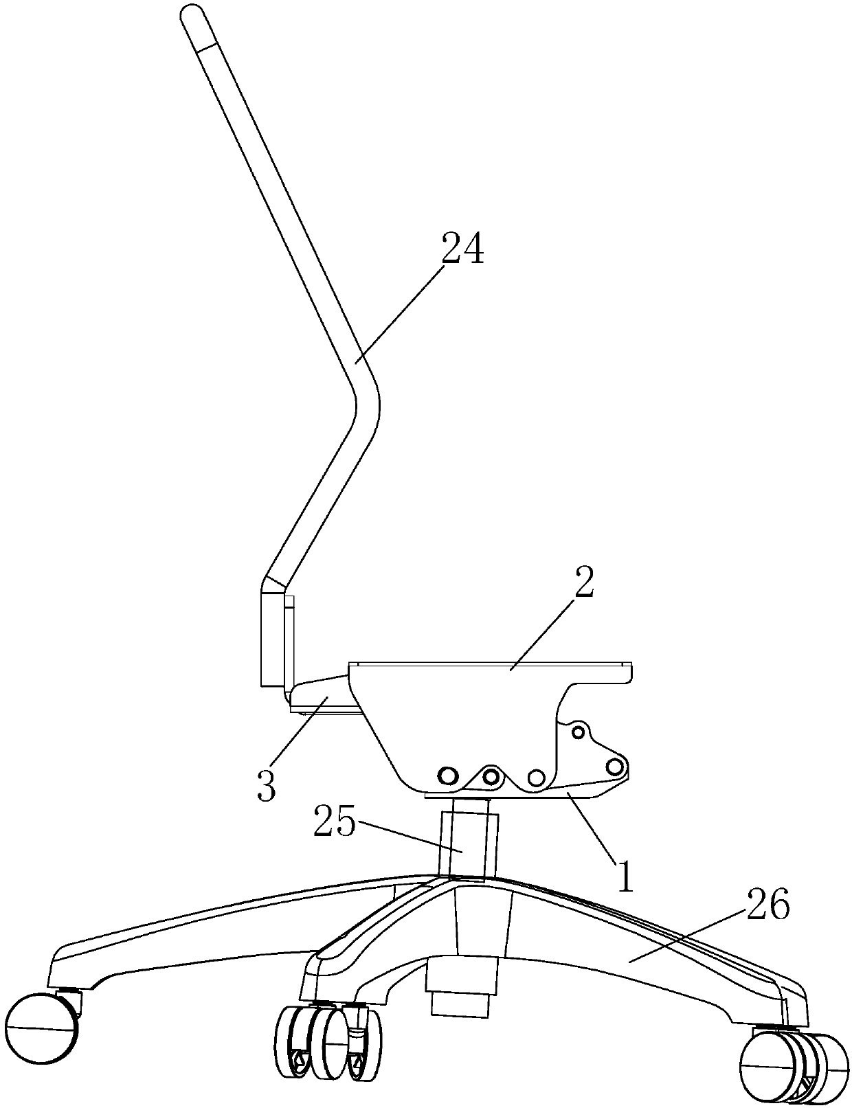
[0057] Embodiment 1: first define the reference orientation of each part of the present invention, the present invention is when the chair is installed and used normally, the front of the chair is the front end and the front, and the rear of the chair includes the position of the back of the chair and the seesaw. Rear end, rear.

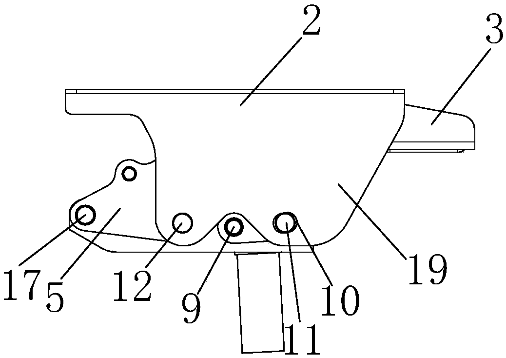
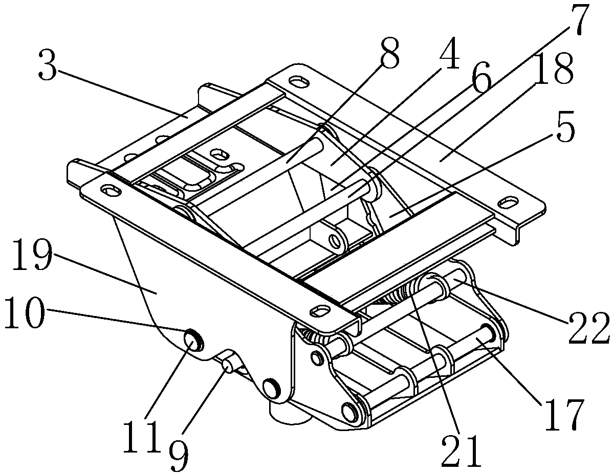
[0058] The synchronous linkage device for the back seat of the present embodiment, such as Figure 1 to Figure 17 As shown, it includes a base 1, a bracket 2 for connecting the seat, a rocker 3 for connecting the seat back, and a first connecting rod 5, a second connecting rod 6 and two symmetrically arranged on both sides of the base 1. A crank 4, two cranks 4 symmetrically arranged on both sides of the base 1; 6. The upper part is hinged by the fourth pin shaft 8; the seesaw 3 and the crank 4 are connected as a whole or the two are integrally formed; the first connecting rod 5 and the second connecting rod 6 are both tilted backward, 1. The secon...

Embodiment 2

[0068] Embodiment 2: In this embodiment, as Figure 18 As shown, the guide avoidance mechanism includes a guide hole 23 and a guide shaft 11, the diameter of the guide hole 23 is larger than the diameter of the guide shaft 11, the guide hole is arranged on the wing plate 19 of the bracket 2, and the corresponding The above-mentioned guide shaft 11 is arranged on the second connecting rod 6 , and the guide shaft 11 passes through the guide hole 23 .


PUM


Abstract

The invention discloses a synchronous back and seat linkage device used for a chair. The device comprises a base, a bearing frame, a wane, a first connection rod and a second connection rod which aresymmetrically arranged on the two sides of the base leftward and rightward, and a crank, the two ends of the crank are respectively hinged to the upper portions of the first connection rod and the second connection rod, and the wane and the crank are connected integrally; the lower portions of the first connection rod and the second connection rod are hinged to the base separately; the lower portions of the first connection rod and the second connection rod are movably connected with the bearing frame, so that the first connection rod and the second connection rod are in linkage with the bearing frame; force is applied to and drives the wane, so that the wane contrarotates and moves forward at the same time, and the front and back portions of the bearing frame ascend at the same time; whenthe wane applied with force contrarotates, hinge points between the first and second connection rods and the crank move forward, therefore a virtual rotary shaft of the wane relative to the ground isalways located nearby the waist, the waist of the human body is regarded as a rotary axis of the upper part of the human body, that is, a back of the chair always closely fits the back of the human body, and the effect of always supporting the waist is achieved.

Description

technical field [0001] The invention relates to the technical field of swivel chairs and office chairs, in particular to a back seat synchronous linkage device for chairs and chairs. Background technique [0002] In the prior art, there is a linkage device for synchronizing the seat and the back of the chair. When the back of the chair is tilted back, the seat moves. Rod linkage and a lever to synchronize the tilt of the seat frame and back frame. The four-bar connection mechanism only includes two cranks, and the cranks are hinged between the base and the seat frame. The lever has two arms and has a fulcrum on the base. Wherein said one arm is integral with said seatback frame. Instead, the other arm acts on the rear of the seat frame and lifts or pulls the rear up or down depending on the angle and direction of inclination of the seat back. [0003] This approach makes the driving force of the back assembly opposed to the restoring force of the seat frame, so people wh...

Claims


Application Information

Patent Timeline
Patent Type & Authority Applications(China)
IPC IPC(8): A47C7/00A47C1/032
CPCA47C1/032A47C1/03255A47C7/00
Inventor 何基蒋小兵
Owner UE FURNITURE CO LTD
Why Eureka
Try Eureka