Chair
A technology of chairs and chair seats, which is applied to chairs, deck chairs, household appliances, etc., can solve problems such as difficult to improve the appearance and lack of self-adaptive gravity, and achieve the effects of overcoming discomfort, good comfort, and flexible settings
- Summary
- Abstract
- Description
- Claims
- Application Information
AI Technical Summary
Problems solved by technology
Method used
Image
Examples
Embodiment 1
[0064] Embodiment 1: first define the reference orientation of each part of the present invention, the present invention is when the chair is installed and used normally, the front of the chair is the front end and the front, and the rear of the chair includes the position of the back of the chair and the seesaw. Rear end, rear.
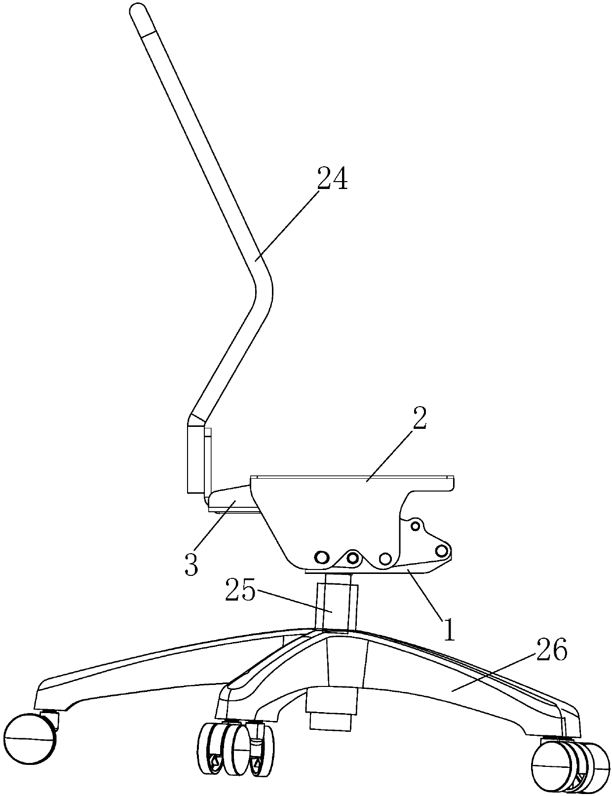
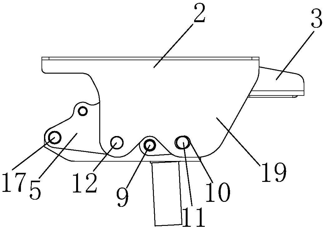
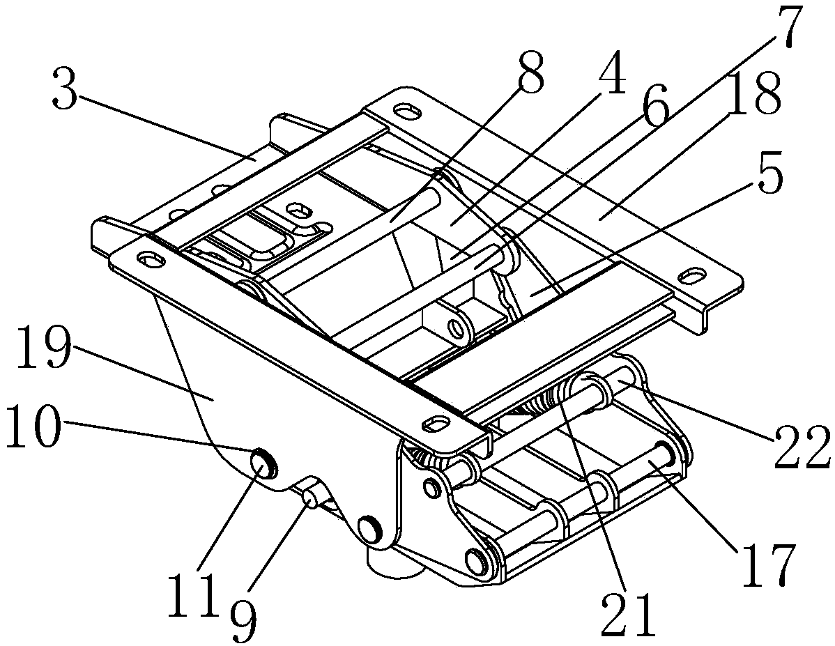
[0065] The chair of the present embodiment, such as Figure 1 to Figure 17 As shown, it includes a base 1, a bracket 2 for connecting the seat, a rocker 3 for connecting the seat back, and a first connecting rod 5, a second connecting rod 6 and two symmetrically arranged on both sides of the base 1. A crank 4, two cranks 4 symmetrically arranged on both sides of the base 1; 6. The upper part is hinged by the fourth pin shaft 8; the seesaw 3 and the crank 4 are connected as a whole or the two are integrally formed; the first connecting rod 5 and the second connecting rod 6 are both tilted backward, 1. The second connecting rods 5 and 6 are arranged ...
Embodiment 2
[0075] Embodiment 2: In this embodiment, as Figure 18 As shown, the guide avoidance mechanism includes a guide hole 23 and a guide shaft 11, the diameter of the guide hole 23 is larger than the diameter of the guide shaft 11, the guide hole is arranged on the wing plate 19 of the bracket 2, and the corresponding The above-mentioned guide shaft 11 is arranged on the second connecting rod 6 , and the guide shaft 11 passes through the guide hole 23 .
Embodiment 3
[0076] Embodiment 3: This embodiment embodies the subject matter to be protected by the claims of the present invention, and the difference between this embodiment and Embodiments 1 and 2 is that: Figure 19 , 20 , 21, 22, 23, and 24, the first connecting rod 5 is at the front of the base 1, and the second connecting rod 6 is a straight connecting rod; the first connecting rod 5 and the bracket 2 pass through the fifth pin 12 hinged, between the rear of the bracket 2 and the base 1, a chute guide mechanism for lifting and lowering the bracket 2 is provided; the second connecting rod 6 and the chute guide mechanism are located in the rear area of the base; this embodiment The chute guide mechanism is similar to the guide avoidance mechanism mentioned in Embodiment 1, 2, but different from it:
[0077] The chute guiding mechanism described in this embodiment includes a waist groove 27 and a guide shaft 11, the waist groove 27 is arranged on the wing plate 19 of the bracket 2,...
PUM
 Abstract
Description
Claims
Application Information
 - R&D
- Intellectual Property
- Life Sciences
- Materials
- Tech Scout
- Unparalleled Data Quality
- Higher Quality Content
- 60% Fewer Hallucinations
Browse by: Latest US Patents, China's latest patents, Technical Efficacy Thesaurus, Application Domain, Technology Topic, Popular Technical Reports.
© 2025 PatSnap. All rights reserved.Legal|Privacy policy|Modern Slavery Act Transparency Statement|Sitemap|About US| Contact US: help@patsnap.com


