Axial locking drill chuck

An axial locking, drill chuck technology, applied in the direction of the chuck, can solve the problems of low safety performance and efficiency of the drill chuck, and achieve the effects of simple structure, increased loosening torque, practical and convenient

Pending Publication Date: 2019-07-26
ROEHM WEIDA MACHINERY (SHANDONG) CO LTD
View PDF0 Cites 0 Cited by
  • Summary
  • Abstract
  • Description
  • Claims
  • Application Information

AI Technical Summary

Problems solved by technology

[0003] The present invention aims at the technical problem of low safety performance and efficiency of existing drill chucks, and provides an axial locking drill chuck with high safety performance and high efficiency.

Method used


Image

  • Axial locking drill chuck
  • Axial locking drill chuck
  • Axial locking drill chuck

Examples


Embodiment Construction

[0031] Specific embodiments of the present invention will be described in detail below with reference to the accompanying drawings.

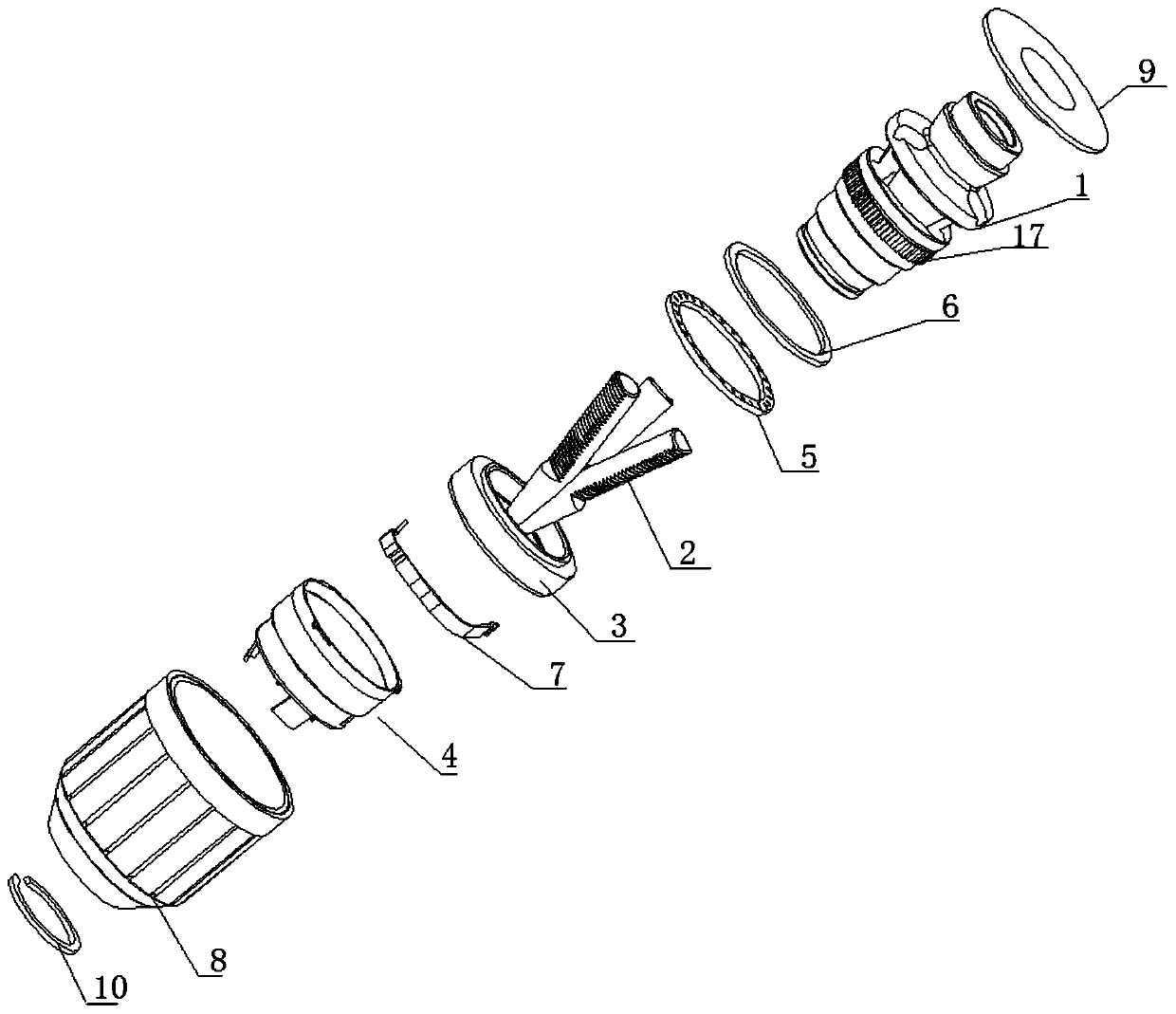
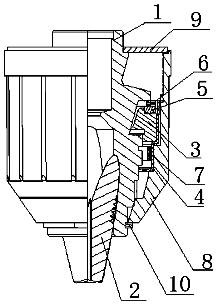
[0032] Such as figure 1 and figure 2 As shown, the present invention includes a drill body 1, jaws 2, nuts 3, nut sleeves 4, bearings 5, bearing pads 6, shrapnel 7, outer casing 8 and rear cover 9, and three jaws 2 are respectively arranged on the drill body In the three oblique holes evenly distributed along the circumferential direction on 1, the screw nut 3 and the jaw 2 are connected by threads, and the threads of the screw nut 3 and the jaw 2 form a thread transmission mechanism, and the bearing 5 is located on the support of the rear end surface of the screw nut 3 In the groove, the bearing pad 6 is arranged between the bearing 5 and the end face of the drill body 1; the nut sleeve 4 is interference-fitted on the nut 3, the jacket 8 and the nut sleeve 4 cooperate, and the rotation of the jacket 8 drives the nut sleeve 4 to rotate , the ...


PUM


Abstract

The invention provides an axial locking drill chuck. The axial locking drill chuck solves the technical problems that an existing drill chuck is low in safety performance and efficiency. The axial locking drill chuck comprises a drill body, clamping claws, a nut, a nut sleeve, a bearing, a bearing pad, an elastic sheet, an outer sleeve and a rear cover. The three clamping claws are arranged in three inclined holes which are evenly distributed in the drill body in the circumferential direction. The nut is in threaded connection with the clamping claws. The nut sleeve is arranged on the nut in an interference fit manner. The elastic sheet is arranged in the nut sleeve. The outer sleeve is matched with the nut sleeve and rotates to drive the nut sleeve to rotate, the nut sleeve drives the nutto rotate, and the nut drives the clamping claws to move. An upper groove and a lower groove are formed in the inner wall of the outer sleeve in the axial direction. The upper end face and the lowerend face of the nut sleeve are provided with an upper positioning claw and a lower positioning claw which are matched with the upper groove and the lower groove correspondingly. The axial locking drill chuck can be widely applied to the technical field of drill tools.

Description

technical field [0001] The invention relates to the technical field of drilling tools, in particular to an axial locking drill chuck. Background technique [0002] The drill chuck is one of the main accessories in the electric tool industry and the machine tool industry. It is widely used in electric hand drills, drilling machines, etc., and is matched with electric drills. The head is generally composed of a drill body, jaws, nuts, and a jacket. The jaws are respectively installed in the equally divided oblique holes of the drill body. The nuts are installed in the nut grooves of the drill body. The threads of the nuts and the grippers form threads The transmission mechanism, the jacket and the nut, and the drill body are fixedly connected. There are threaded holes or taper holes at the rear of the drill body. The driving drill body drives the jaws and the clamped tool to rotate synchronously; however, during the working hours of the drill chuck, due to the high vibration ...

Claims


Application Information

Patent Timeline
Patent Type & Authority Applications(China)
IPC IPC(8): B23B31/12
CPCB23B31/123
Inventor 于成银魏宁波
Owner ROEHM WEIDA MACHINERY (SHANDONG) CO LTD
Why Eureka
Try Eureka