
Drill chuck capable of increasing loosening torque

A drill chuck, loosening technology, applied in the direction of the chuck, etc., can solve the problem of exiting from the self-locking state, and achieve the effect of reasonable structure, simple production, and increased loosening torque.

Pending Publication Date: 2018-06-29
ZHE JIANG SAN OU MASCH CO LTD
View PDF2 Cites 1 Cited by
  • Summary
  • Abstract
  • Description
  • Claims
  • Application Information

AI Technical Summary

Problems solved by technology

[0004] The purpose of the present invention is to provide a drill chuck with increased loosening torque to solve the problem that the drill chuck exits the self-locking state due to emergency stop in the case of high-speed rotation

Method used


Image

  • Drill chuck capable of increasing loosening torque
  • Drill chuck capable of increasing loosening torque
  • Drill chuck capable of increasing loosening torque

Examples


Embodiment Construction

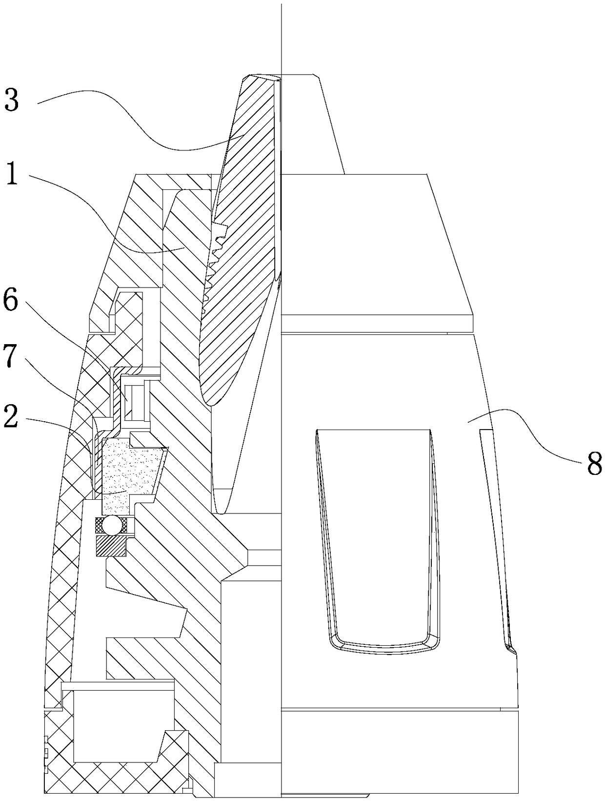
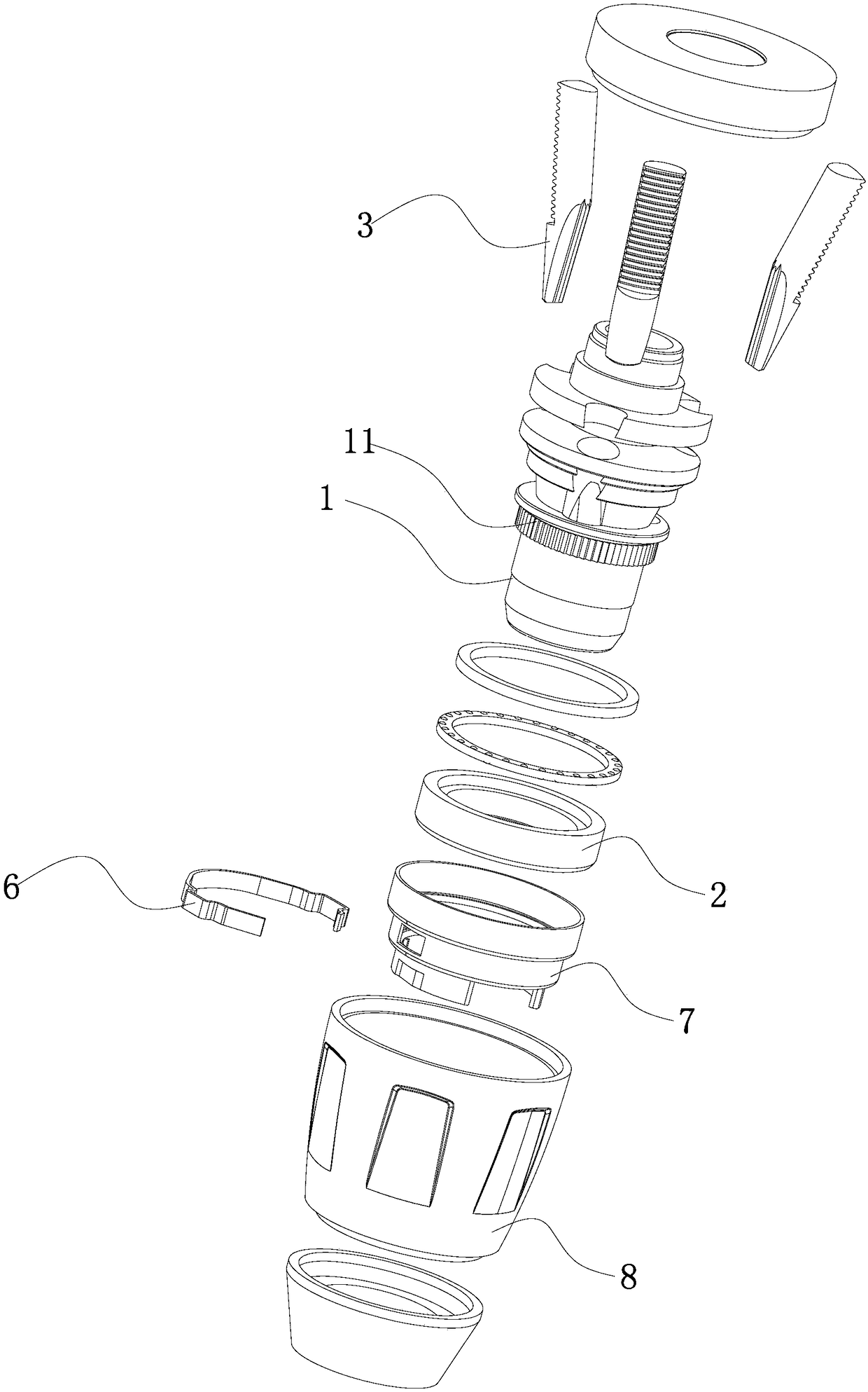
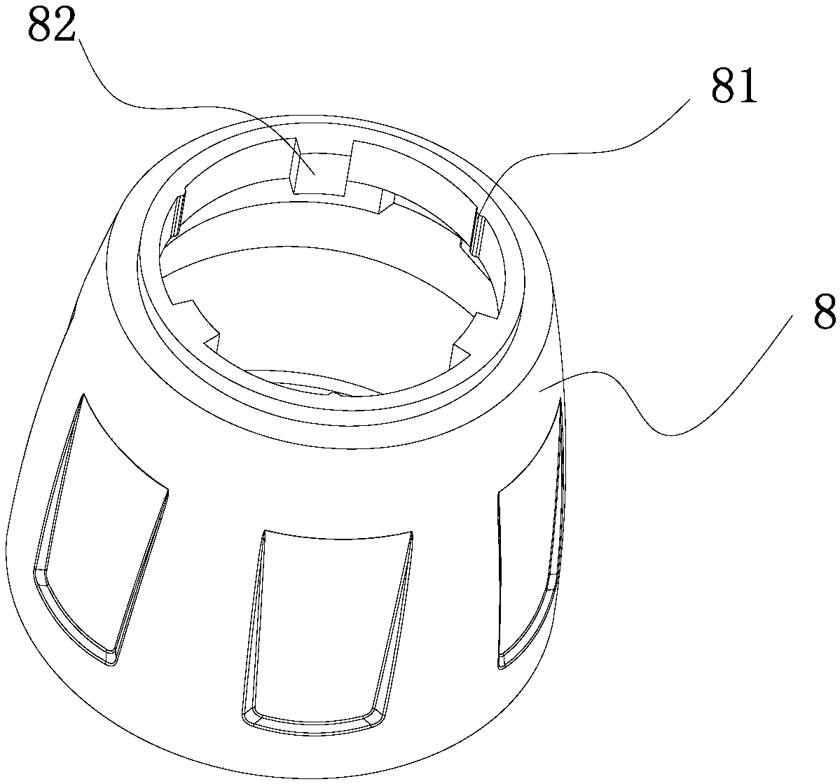
[0020] Refer to attached picture. The drill chuck with increased loosening torque provided by the present invention includes a rotating sleeve 8, a drill body 1, a nut 2, a nut sleeve 7, jaws 3, and a self-locking structure, and the self-locking structure includes teeth 11 and spring plates 6 , the tooth 11 is on the drill body 1, the spring leaf 6 has a locking end 61 that matches the tooth, and the rotating sleeve 8 has a part 84 that is connected to the spring leaf 6 in the self-locking state and is not self-locking. The position 83 connected with the spring leaf, the two sides of the spring leaf 6 have lock end protrusions 62 and positioning protrusions 63 respectively, and the lock end protrusions 62 and positioning protrusions 63 are respectively stuck on the two sides of the nut sleeve. On the first mounting hole 72, a cam surface 85 for the lock end protrusion 62 is also provided in the rotating sleeve.

[0021] The drill chuck is also provided with a self-locking and...


PUM


Abstract

The invention provides a drill chuck capable of increasing loosening torque. The drill chuck is characterized in that a self-locking loosening-prevention structure is also arranged between a rotary sleeve and a nut sleeve; the self-locking loosening-prevention structure comprises an inclined plane and a matching part matched with the inclined plane; the matching part and the inclined plane can berelatively rotated and clutched in the circumferential direction of the drill chuck; when the drill chuck is in a self-locking state, the matching part and the inclined plane are in a pitched frictionmatching state; and when the drill chuck withdraws a self-locking state and is in a non-self-locking state, the matching part is disengaged from the inclined plane. According to the drill chuck capable of increasing the loosening torque disclosed by the invention, high return-stop friction force is provided in the self-locking state through matching of the clutched inclined plane, so that the loosening torque is increased and an effect of preventing loosening is achieved; and in an occasion of high-speed rotation of the drill chuck, the self-locking state can be withdrawn due to an inertia effect when sudden stop occurs, and the nut sleeve is manufactured without needing to use a spring steel material and thermal treatment is also not needed. Compared with the prior art, the drill chuck disclosed by the invention has a reasonable structure, is simple to manufacture, and has good locking and loosening prevention performance.

Description

technical field [0001] The invention relates to a drill chuck. Background technique [0002] In the prior art, the drill chuck is equipped with a drill body, jaws, nuts, bearings, gaskets, rotating sleeves, and rear sleeves. By rotating the nut, the jaws are driven to move forward or backward to make the chuck clamp Tighten or loosen drilling tools. The self-locking structure in the drill chuck is a structure that prevents the drill from being loosened by the reaction force it receives when the drill chuck is in operation. It generally consists of parts with spring sheets and teeth on the drill body. To cooperate. This kind of self-locking drill chuck will exit the self-locking state due to inertia once it stops suddenly in the case of high-speed rotation. [0003] The locking structure of the hand-tightening drill chuck of U.S. Patent No. US5765839A is based on the existing hand-tightening drill chuck. There are grooves and protrusions inside the front cover to match th...

Claims


Application Information

Patent Timeline
Patent Type & Authority Applications(China)
IPC IPC(8): B23B31/12
CPCB23B31/123
Inventor 周文华吴云贵卢启荣
Owner ZHE JIANG SAN OU MASCH CO LTD
Learn More