A different plane welding technology and welding equipment using the same

A plane welding and technology technology, applied in the field of parts processing, can solve the problems of consuming manpower and material resources, increasing processing and manufacturing costs, affecting the focal length of camera lenses, etc., to achieve the effect of saving manpower and material resources and reducing costs

Active Publication Date: 2021-10-01
SUZHOU LINGYU ELECTRONICS TECH CO LTD
View PDF0 Cites 0 Cited by
  • Summary
  • Abstract
  • Description
  • Claims
  • Application Information

AI Technical Summary

Problems solved by technology

However, due to the different structures of the two parts, when performing two-point welding, when the two parts are in contact with one of the welding points, the other welding point is often difficult to match and contact due to the height difference, so it is difficult to guarantee the quality of the product. In addition, the height difference also affects the focal length of the camera lens, which can also cause errors in the positioning of the product
Therefore, the two products can only be divided into two stations for welding, which consumes more manpower and material resources and increases the cost of processing and manufacturing.

Method used


Image

  • A different plane welding technology and welding equipment using the same
  • A different plane welding technology and welding equipment using the same
  • A different plane welding technology and welding equipment using the same

Examples


Embodiment Construction

[0028] The present invention will be described in further detail below in conjunction with the accompanying drawings.

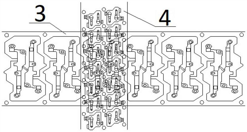
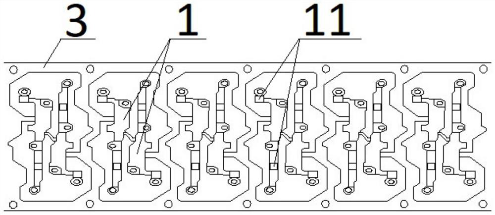
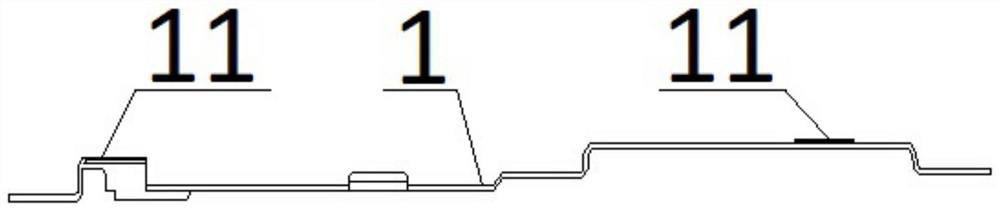
[0029] figure 1 Schematically showing a top perspective view of strips and parts being welded by a different planar welding technique according to an embodiment of the present invention, figure 2 shown figure 1 Top view of large strips and large parts in , image 3 shown figure 2 Side view of the large part in, Figure 4 shown figure 1 Top view of small strips and small parts in . Such as Figure 1-4 As shown, this method is mainly to design the structure of the large part 1 and the small part 2 to be welded to a certain extent, and then feed them on a large material belt 3 and a small material belt 4 respectively, and use the corresponding The equipment simultaneously pulls the large strip 3 and the small strip 4 at different heights, and performs welding work in due course.

[0030] In this embodiment, one large part 1 is welded with two small par...


PUM


Abstract

The invention relates to the field of parts processing and discloses a different plane welding technology. The main steps of this technology include: setting up the large part to be welded so that the two welding parts on it have a difference in height; setting up the small part to be welded so that the height of the two welding areas on it is The outer side of one of them forms a Z-shaped bend extending to the bottom; the large and small strips are set on a welding device and pulled, and the large and small parts are loaded; the large strip Fix with small strips, make large parts and small parts match and weld. A different plane welding technology in the present invention designs the structures of the two parts to be processed, so that the two parts can cooperate with each other, and the camera can focus accurately, so that the two can perform welding work stably, saving manpower and material resources , reducing the cost of processing and manufacturing.

Description

technical field [0001] The invention relates to the field of parts processing, in particular to a different plane welding technology and welding equipment using the same. Background technique [0002] During the processing of metal parts and equipment, it is often necessary to weld two parts together, and this process is generally operated with a single-station positioning jig. First, one of the parts to be welded is placed on the jig for separate positioning. Then another part to be welded is placed in a relatively positioned position, and then put into a pressing fixture to fix the two parts to be welded, and then a welding torch can be used to weld it. [0003] However, the above-mentioned method of using a single-station positioning jig for welding processing requires manual operation for positioning. Low, and the quality of processing is often difficult to guarantee because of the uneven technical level of the operators. [0004] In order to solve the shortcomings of ...

Claims


Application Information

Patent Timeline
Patent Type & Authority Patents(China)
IPC IPC(8): B23K37/04B23K37/00
CPCB23K37/00B23K37/04
Inventor 田晓锋
Owner SUZHOU LINGYU ELECTRONICS TECH CO LTD
Why Eureka
Try Eureka