Tyre anti-skid device

An anti-skid device and tire technology, applied in the directions of wheels, wheel accessories, transportation and packaging, etc., to achieve good application prospects, improve safe driving, and facilitate storage

Pending Publication Date: 2019-07-26
王强
View PDF0 Cites 2 Cited by
  • Summary
  • Abstract
  • Description
  • Claims
  • Application Information

AI Technical Summary

Problems solved by technology

[0003] In order to overcome the disadvantages existing in the practical application of the existing anti-skid chains, the present invention provides a device with several sets of telescopic arm devices, which are located inside the hub of the automobile wheel when not in use at ordinary times. Personnel operate the large conical gear located in front of the fixed plate in the middle of the car wheel, and drive several sets of telescopic arm equipment to extend the rectangular movable rods forward, and then the outer end of the rectangular movable rod is higher than the surface of the tire, and the rectangular movable rod is fixed by the positioning plate to prevent Displacement, when the vehicle is moving, the pointed part of the outermost end of the rectangular movable rod can be effectively inserted on the surface of snow or ice, preventing the tires of the moving vehicle from slipping, thereby effectively improving the safety of the vehicle on the snow-covered and icy ground

Method used


Image

  • Tyre anti-skid device
  • Tyre anti-skid device
  • Tyre anti-skid device

Examples


Embodiment Construction

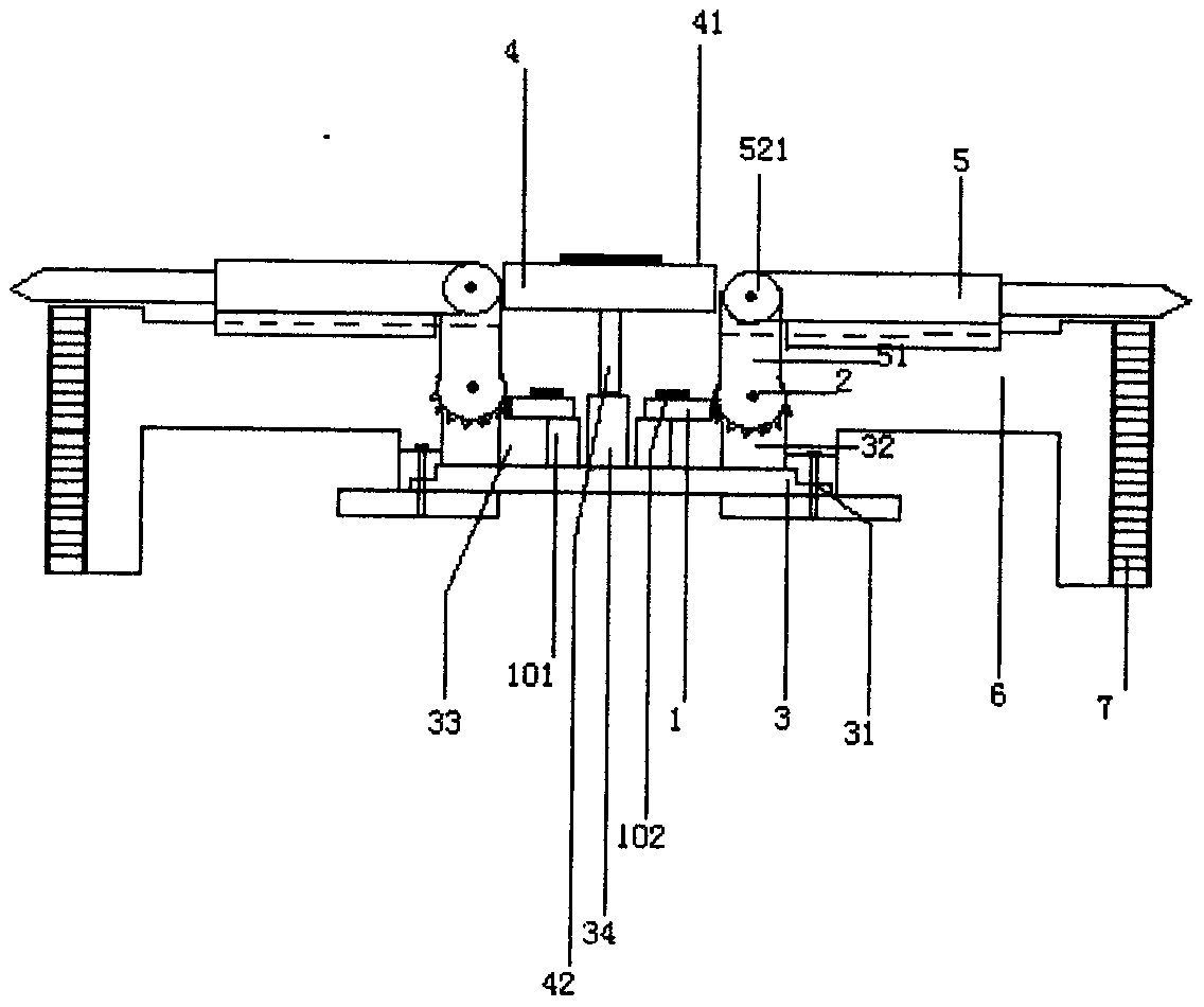
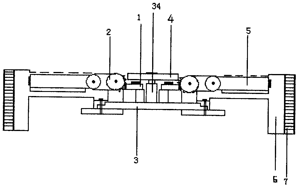
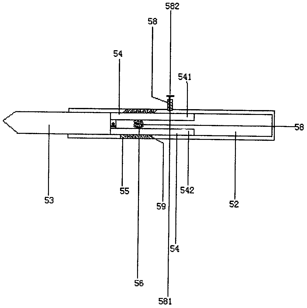
[0015] figure 1 , 2 , Shown in 3, 4, a kind of tire anti-skid device, comprises the conical large gear 1 that has opening in the middle, helical gear 2, also has fixed disk 3, positioning disk 4, telescopic arm equipment 5, ring fixed disk 3 The outer side has a plurality of fixing holes 31 at certain equidistant intervals, and five supporting plates 32 are welded at certain equidistant intervals at the front end of the ring fixed disk 3, and a bearing seat is welded on the front upper side end of each supporting plate 32, and the bearing A shaft is installed in the bearing inner ring of the seat, and the helical gear 2 has the same five, and the shaft hole in the middle of each helical gear 2 is installed horizontally on the upper end of the shaft of each support plate bearing seat, and screwed into the screw through a nut The upper external thread is fixed, and the rear end of each helical gear 2 is a semicircular helical tooth structure. A bearing seat 33 is welded in the ...


PUM


Abstract

The invention relates to a tyre anti-skid device which comprises a conical gear and a plurality of helical gears and is characterized by further comprising a fixed disk, a positioning disk and a plurality of sets telescopic arm equipment, wherein a plurality of supporting plates are installed around the front side end of the fixed disk at a certain equal distance interval, a bearing seat is installed on the front middle part of the fixed disk, an integrally formed sleeve pipe is arranged at the rear end of a middle opening of the conical large gear, the rear end of the sleeve pipe is longitudinally distributed, an inner ring of the bearing on the front middle part of the fixed disk sleeves the rear end of the sleeve pipe, and the helical gears are annularly distributed at the side end of the conical large gear; and the rear ends of the telescopic arm equipment are installed at the front ends of the helical gears correspondingly, an internal thread pipe is installed on the inner side ofthe bearing seat located on the front middle part of the fixed disk, the rear end of the fixed disk is installed in the internal thread pipe, and the fixed disk is installed at the middle of the inner side of a vehicle hub. When a vehicle of the tyre anti-skid device travels, the pointed cone part of the outermost end of a rectangular movable rod can be effectively inserted in the surface of snowor ice, vehicle tyres are prevented from skidding during traveling, and therefore safe running of the vehicle on the snow-covered and ice-covered ground is effectively improved.

Description

technical field [0001] The invention relates to the field of automobile supporting equipment, in particular to a tire anti-skid device. Background technique [0002] When the vehicle is in use, if it is driven on snowy or soily roads, especially on icy roads after the snow has melted, the wheels will easily slip, which will easily lead to operational failure and dangerous traffic accidents. At present, the solution to wheel slippage is mainly to install anti-skid chains on the surface of the wheels, but the application of anti-skid chains has the following disadvantages. First, the installation is inconvenient. It takes more than two people to install the wheels of large vehicles, which is time-consuming and laborious. Second, the anti-skid chains have poor force and grip effect, so that the anti-skid effect is not good, especially when going up and downhill, there is still a phenomenon of wheel slippage, which may cause traffic accidents; third, the anti-skid chains are due...

Claims


Application Information

Patent Timeline
IPC IPC(8): B60B15/00
CPCB60B15/00
Inventor 王强
Owner 王强
Why Eureka
Try Eureka