
Lifting appliance of concrete pipe piles

A technology for concrete pipe piles and spreaders, applied in the field of spreaders, can solve the problems of heavy pipe piles and hooks, prone to casualties, waste of human resources, etc., so as to reduce the separation of the lifting mechanism from the spreader frame and improve the safety. , the effect of saving human resources

Active Publication Date:
View PDF9 Cites 7 Cited by
  • Summary
  • Abstract
  • Description
  • Claims
  • Application Information

AI Technical Summary

Problems solved by technology

[0004] However, in the process of pipe pile hoisting, it is necessary for "two operators to stand beside the two ends of the stacked pipe piles in person, and the two operators will respectively tie up the ends of the same pipe pile and then hang the rope on the The on-site operation of "on the hook of the crane" needs to be improved because the pipe pile and the hook are heavy, which wastes human resources and is also prone to casualties.

Method used


Image

  • Lifting appliance of concrete pipe piles
  • Lifting appliance of concrete pipe piles
  • Lifting appliance of concrete pipe piles

Examples


Embodiment Construction

[0037] The following will clearly and completely describe the technical solutions in the embodiments of the present invention with reference to the drawings in the embodiments of the present invention. It should be noted that if there is a directional indication (such as up, down, left, right, front, back...) in the embodiment of the present invention, the directional indication is only used to explain the position in a certain posture (as shown in the accompanying drawing). If the specific posture changes, the directional indication will also change accordingly. In addition, if there are descriptions involving "first", "second" and so on in the embodiments of the present invention, the descriptions of "first", "second" and so on are only for descriptive purposes, and should not be interpreted as indicating or implying Its relative importance or implicitly indicates the number of technical features indicated. Thus, the features defined as "first" and "second" may explicitly o...


PUM


Abstract

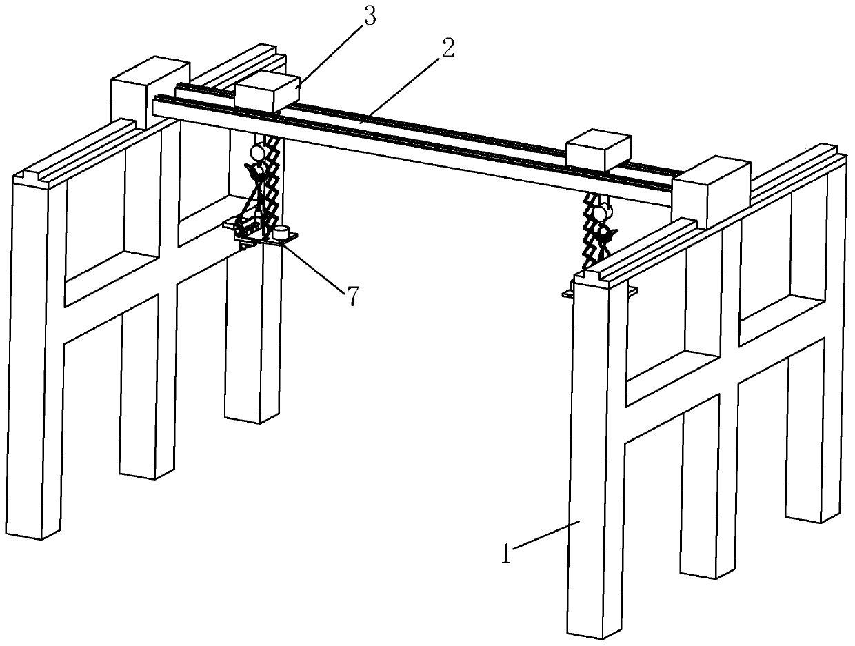
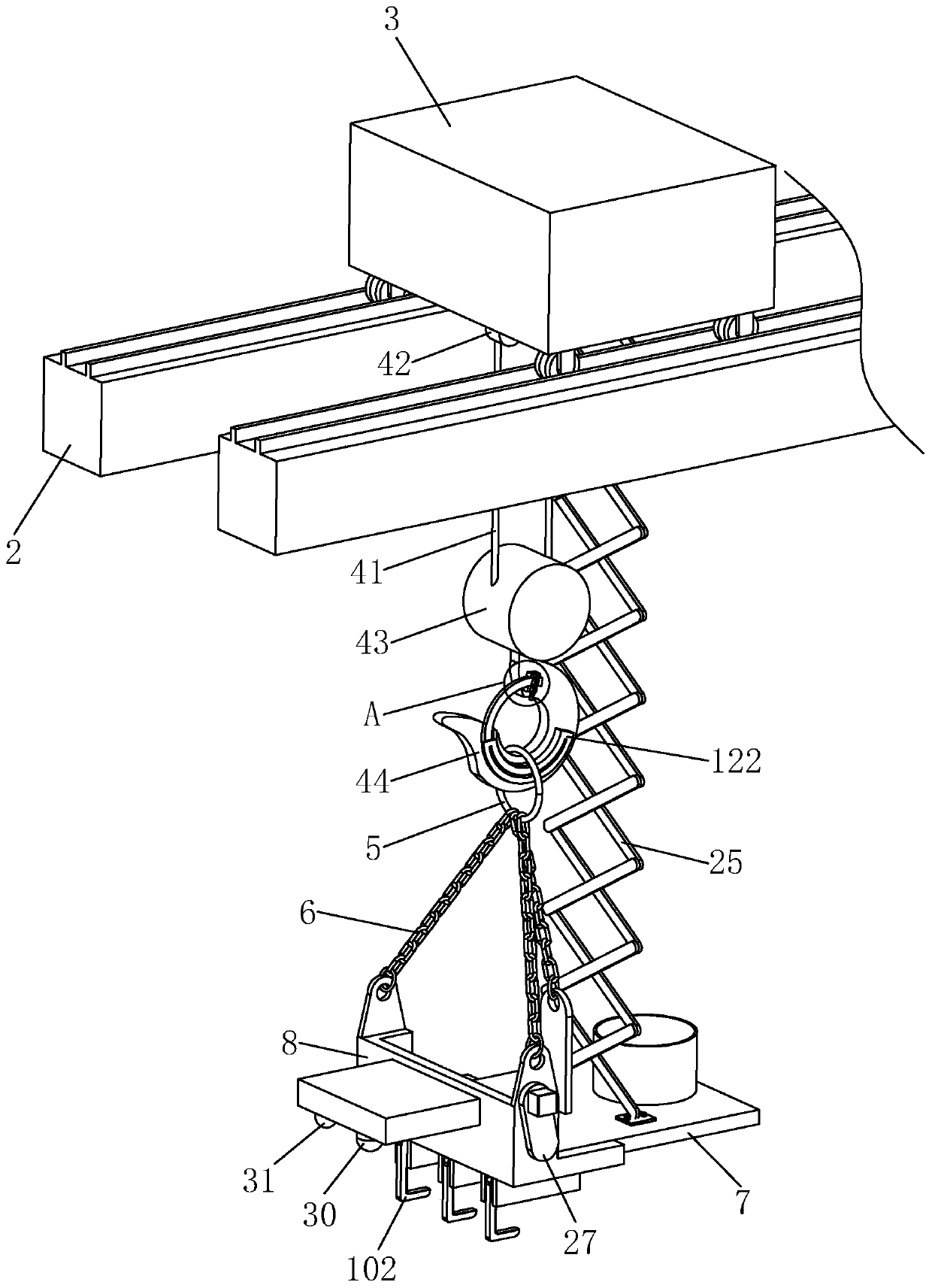
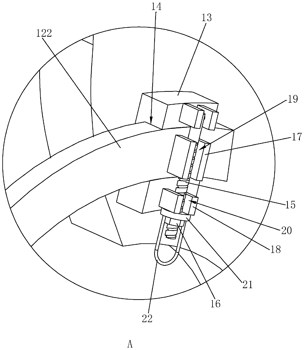
The invention relates to a lifting appliance, in particular to a lifting appliance of concrete pipe piles. According to the technical scheme, a support, a transverse supporting rail, two conveying vehicles and lifting mechanisms are involved, wherein the transverse supporting rail is arranged on the top of the support in a sliding mode in the horizontal direction, the two conveying vehicles are arranged on the transverse supporting rail in a sliding mode in the length direction of the transverse supporting rail correspondingly, and the lifting mechanisms are correspondingly connected to the bottoms of the conveying vehicles; the lifting mechanisms are connected with lifting appliance frame bodies through hanging rings and a chain in a matched mode, and a lifting hook units are installed onthe lifting appliance frame bodies; and the lifting hook units comprise mounting bases and main shafts, wherein the mounting bases are fixedly arranged on the lifting appliance frame bodies, the mainshafts are rotationally arranged on the mounting bases in a rotating and penetrating mode, lifting hooks are pivoted to the main shafts in the length directions of the main shafts, and the mounting bases are provided with driving mechanisms used for driving the lifting hooks to rotate up and down in the axial length directions of the main shafts so as to hook the pipe piles. The lifting appliancedoes not need people to run beside the pipe piles, and then the pipe piles are bundled and then hoisted, the operation is simple, the hoisting process is stable, the manpower resources are saved, andthe operation safety is improved as well at the same time.

Description

technical field [0001] The present invention relates to a spreader, more specifically, it relates to a concrete pipe pile spreader. Background technique [0002] Concrete pipe piles are commonly used components in the construction field. In civil buildings, buildings with more than 5 floors usually need piles to strengthen the foundation; in large industrial buildings, it is necessary to use a large number of pipe piles as the foundation, and as the depth of piles increases, the longer and thicker the pipe piles required . [0003] In the hoisting process of pipe piles in the prior art, the operator usually needs to stand beside the pipe piles that are stacked and stored, and then tie the two ends of the pipe piles to be lifted with the help of ropes and hang the ropes on the hooks of the crane, and then The hook is driven by the crane to move to achieve the purpose of lifting the pipe pile. [0004] However, in the process of pipe pile hoisting, it is necessary for "two ...

Claims


Application Information

Patent Timeline
Patent Type & Authority Applications(China)
IPC IPC(8): B66C19/00B66C11/00B66C13/16B66C13/22
CPCB66C11/00B66C13/16B66C13/22B66C19/00
Inventor 张应棋
Learn More