
Positioning pin mounting seat

A positioning pin and mounting seat technology, applied in the field of vehicles, can solve the problems of inconvenient fine-tuning of the position of the positioning pin, affecting the installation accuracy of the positioning pin, and complicated operation.

Inactive Publication Date: 2021-03-05
BEIJING BORGWARD AUTOMOBILE CO LTD
View PDF6 Cites 0 Cited by
  • Summary
  • Abstract
  • Description
  • Claims
  • Application Information

AI Technical Summary

Problems solved by technology

[0003] The installation method in the existing scheme is very inconvenient to fine-tune the position of the positioning pin. If you want to adjust the position of the positioning pin, you must block the mounting threaded hole of the lower mold, and then use the CNC machine tool to process a new bottom hole according to the latest position. Tapping by a fitter, the operation is cumbersome
Moreover, such a change will leave part of the welding body around the new positioning pin hole, which will affect the installation accuracy of the positioning pin
At the same time, this change is irreversible. If the desired effect is not achieved after adjustment, and you want to return to the original position, you must repeat the above steps
Therefore, there is room for improvement in the above techniques

Method used


Image

  • Positioning pin mounting seat
  • Positioning pin mounting seat
  • Positioning pin mounting seat

Examples


Embodiment Construction

[0043] Embodiments of the present invention are described in detail below, examples of which are shown in the drawings, wherein the same or similar reference numerals designate the same or similar elements or elements having the same or similar functions throughout. The embodiments described below by referring to the figures are exemplary only for explaining the present invention and should not be construed as limiting the present invention.

[0044] In describing the present invention, it should be understood that the terms "center", "longitudinal", "transverse", "length", "width", "thickness", "upper", "lower", "front", " Back", "Left", "Right", "Vertical", "Horizontal", "Top", "Bottom", "Inner", "Outer", "Clockwise", "Counterclockwise", "Axial" , "radial", "circumferential" and other indicated orientations or positional relationships are based on the orientations or positional relationships shown in the drawings, which are only for the convenience of describing the present ...


PUM


Abstract

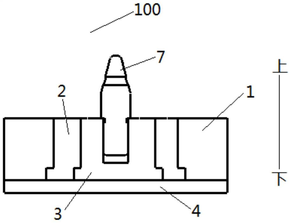
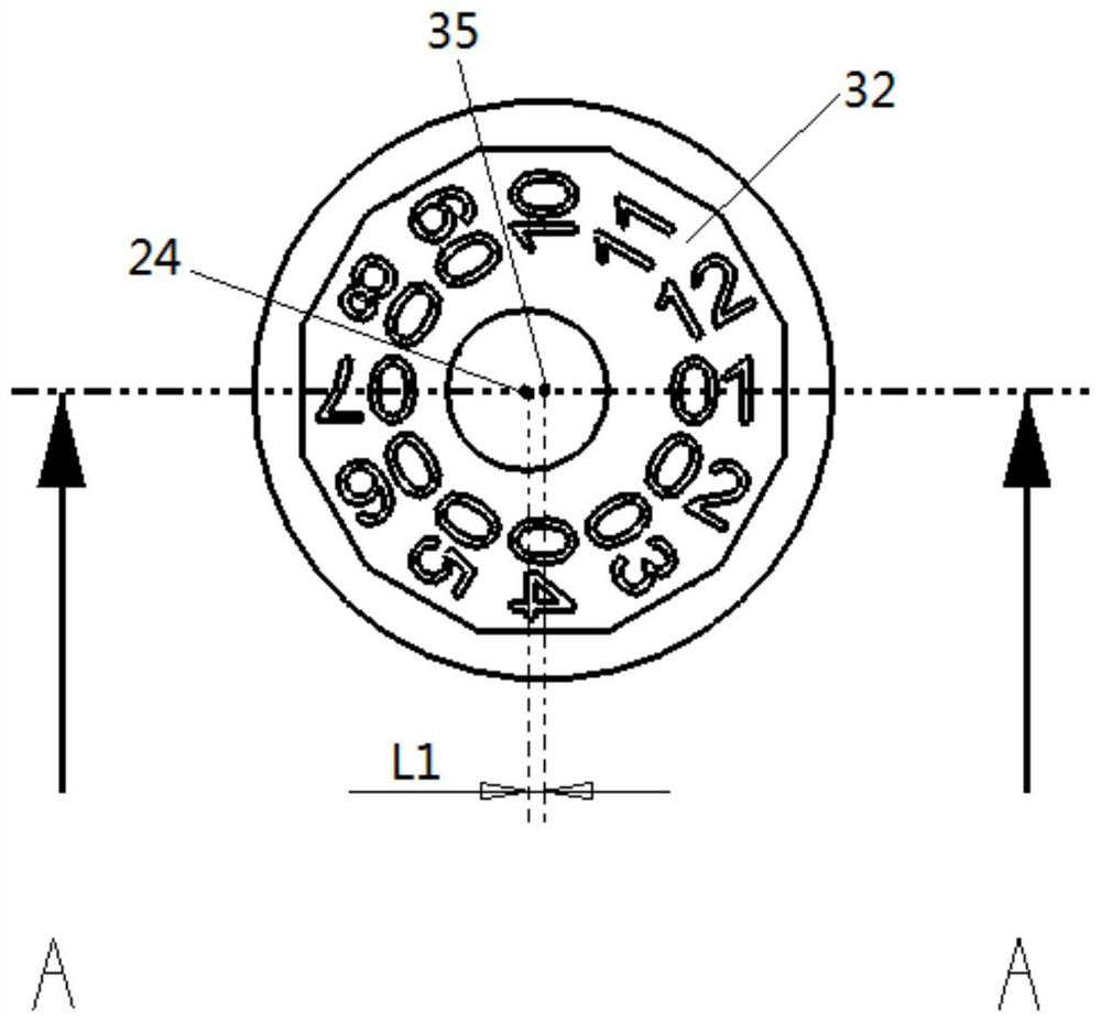
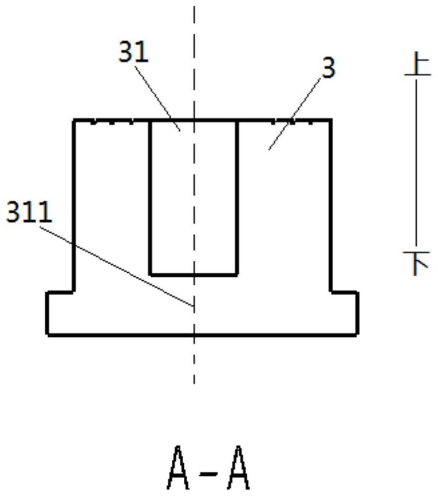
The invention discloses a positioning pin mounting seat. The positioning pin mounting seat comprises a mounting base, an outer adjusting piece and an inner adjusting piece. The outer adjusting piece is embedded in the mounting base and can rotate around the central axis of the outer adjusting piece. The inner adjusting piece is embedded in the outer adjusting piece and can rotate around the central axis of the inner adjusting piece, the central axis of the inner adjusting piece does not coincide with the central axis of the outer adjusting piece, a positioning pin hole is formed in the inner adjusting piece, and a positioning pin is arranged in the positioning pin hole in a matched manner. According to the positioning pin mounting seat, the horizontal position of the positioning pin in a tool can be changed by adjusting the angles of the outer adjusting piece and the inner adjusting piece, and then the purpose of accurately positioning a part in the tool is achieved.

Description

technical field [0001] The invention relates to the technical field of vehicles, in particular to a positioning pin mounting seat. Background technique [0002] At present, the competition in the automobile market is becoming increasingly fierce. In order to occupy a place in the market, various automobile companies are constantly developing new models, and the requirements for production precision are also getting higher and higher. Restricted by factors such as machining accuracy of machine tools and the technical level of operators, the molds and fixtures developed by the manufacturing department often need to be debugged for a long time before the official mass production of the model, in order to achieve the pass rate required by the quality department. The problem of precise positioning is an important factor affecting the pass rate. When the quality department measures the workpiece with three coordinates, it also needs to repeatedly adjust the inspection tool or mea...

Claims


Application Information

Patent Timeline
Patent Type & Authority Applications(China)
IPC IPC(8): B25B11/00
CPCB25B11/00
Inventor 李书建
Owner BEIJING BORGWARD AUTOMOBILE CO LTD
Learn More