
Drilling machine for mining

A technology for drilling rigs and mines. It is applied in the direction of drill pipes, drill pipes, and earthwork drilling. It can solve the problems of construction environment pollution, low work efficiency, and easy to raise a large amount of rock debris and dust, so as to achieve wide applicability and avoid pollution effect

Inactive Publication Date: 2021-10-29
XUZHOU HUAFENG MEASUREMENT & CONTROL TECH
View PDF5 Cites 0 Cited by
  • Summary
  • Abstract
  • Description
  • Claims
  • Application Information

AI Technical Summary

Problems solved by technology

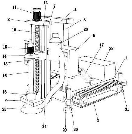
[0002] Drilling rig is a complex set of machines, which is composed of machines, units and mechanisms. Drilling rig is a mechanical device that drives drilling tools to drill underground to obtain physical geological data during exploration or mineral resource development. It is also called drilling rig. The function is to drive the drilling tool to break the rock at the bottom of the hole, and to lower or lift the drilling tool in the hole, which can be used to drill cores, ore cores, cuttings, gas samples, liquid samples, etc., to prove the underground geology and mineral resources, etc. , but the working efficiency of most of the existing drilling rigs is low, and most of the drilling rigs are not easy to adjust the working angle, and the existing drilling rigs are easy to raise a large amount of rock debris and dust during the drilling process, which is harmful to construction The environment causes pollution and affects the health of the staff

Method used


Image

  • Drilling machine for mining
  • Drilling machine for mining
  • Drilling machine for mining

Examples


Embodiment Construction

[0017] The present invention will be described in further detail below in conjunction with the accompanying drawings.

[0018] The specific implementation manner of the present invention will be further described below in conjunction with the accompanying drawings. Wherein the same components are denoted by the same reference numerals.

[0019] It should be noted that the words "front", "rear", "left", "right", "upper" and "lower" used in the following description refer to the directions in the drawings, and the words "inner" and "outer ” refer to directions towards or away from the geometric center of a particular part, respectively.

[0020] In order to make the content of the present invention more clearly understood, the technical solutions in the embodiments of the present invention will be clearly and completely described below in conjunction with the drawings in the embodiments of the present invention.

[0021] In conjunction with the accompanying drawings, a drillin...


PUM


Abstract

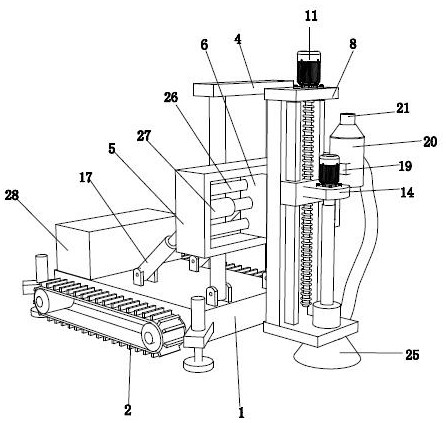
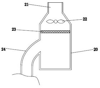
The invention discloses a drilling machine for mining. The drilling machine comprises a rack and conveying crawler belts arranged on the two sides of the rack, wherein two mounting columns are rotatably arranged at the front end of the rack; connecting plates are connected to the ends of the two mounting columns; mounting frames are arranged at the front ends of the two mounting columns; sliding blocks are arranged in the mounting frames; mounting plates are arranged at the front ends of the sliding blocks; top plates and bottom plates are arranged at the upper ends and the lower ends of the mounting plates correspondingly; lead screws are rotatably arranged between the top plates and the bottom plates; two guiding blocks located on the two sides of the lead screws correspondingly are arranged on the front sides of the mounting plates; lifting plates slidably connected with the two guiding blocks are connected to the lead screws in a threaded mode; motor bases are arranged at the front ends of the lifting plates; second motors are arranged at the upper ends of the motor bases; and drilling rods located at the lower ends of the motor bases are arranged at the output ends of the second motors. Compared with the prior art, the drilling machine has the advantages that the drilling angle can be adjusted according to the requirements, and pollution of dust to the construction environment can be avoided.

Description

technical field [0001] The invention relates to the technical field of mining equipment, in particular to a drilling rig for mining. Background technique [0002] Drilling rig is a complex set of machines, which is composed of machines, units and mechanisms. Drilling rig is a mechanical device that drives drilling tools to drill underground to obtain physical geological data during exploration or mineral resource development. It is also called drilling rig. The function is to drive the drilling tool to break the rock at the bottom of the hole, and to lower or lift the drilling tool in the hole, which can be used to drill cores, ore cores, cuttings, gas samples, liquid samples, etc., to prove the underground geology and mineral resources, etc. , but the working efficiency of most of the existing drilling rigs is low, and most of the drilling rigs are not easy to adjust the working angle, and the existing drilling rigs are easy to raise a large amount of rock debris and dust d...

Claims


Application Information

Patent Timeline
IPC IPC(8): E21B7/02E21B15/00E21B15/04E21B19/081E21B21/015
CPCE21B7/02E21B7/024E21B15/003E21B15/04E21B19/081E21B21/011E21B21/015
Inventor 杜长亭王愁支光斗宫配金
Owner XUZHOU HUAFENG MEASUREMENT & CONTROL TECH
Learn More