Grout injector

A grouting device and elastic casing technology, which is applied in construction, infrastructure engineering and other directions, can solve the problems of the grouting device sliding out of the steel pipe, the insufficient friction force of the rubber pipe, and the inability of the grouting device to continue to penetrate into the steel pipe, etc. The effect of friction

Pending Publication Date: 2019-07-26
RAILWAY ENG RES INST CHINA ACADEMY OF RAILWAY SCI +1
View PDF0 Cites 1 Cited by
  • Summary
  • Abstract
  • Description
  • Claims
  • Application Information

AI Technical Summary

Problems solved by technology

If the pressure exceeds this value, the grouting device will have insufficient friction between the rubber tube part and the inner wall of the steel pipe due to the excessive grouting pressure at the bottom, causing the grouting device to slip out of the steel pipe and the hole sealing will fail
[0006] (2) The grouting device in the prior art cannot solve the problem of blockage in the steel pipe
For example, when the steel pipe falls into mud and hardens, it is easy to make the grouter unable to continue to penetrate the steel pipe

Method used


Image

  • Grout injector
  • Grout injector
  • Grout injector

Examples


Embodiment Construction

[0029] In order to make the technical solutions and advantages of the present invention clearer, the present invention will be further described in detail below in conjunction with the accompanying drawings and specific embodiments.

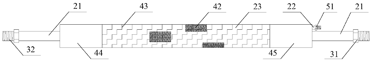
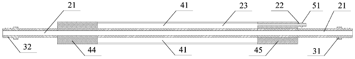
[0030] figure 2 It is a schematic structural view of the injector in the embodiment of the present invention, image 3 It is a sectional view of the injector in the embodiment of the present invention. Such as figure 2 and image 3 As shown, the grouting device includes: a through steel pipe 21, an air intake pipe 22 and an elastic sleeve 23;

[0031] The upper end of the penetrating steel pipe 21 is provided with a grouting interface 31, and the lower end is provided with a high-pressure nozzle interface 32 for connecting with a high-pressure nozzle;

[0032] The elastic sleeve 23 is sleeved on the outside of the through steel pipe 21, and the lower end of the elastic sleeve 23 is fixed on the through steel pipe 21; the middle part of the ...


PUM


Abstract

The invention provides a grout injector. The grout injector comprises a penetrating steel pipe, a gas feeding pipe and an elastic sleeve pipe; a grout injecting connector is arranged at the upper endof the penetrating steel pipe, and a high-pressure nozzle connector used for being connected with a high-pressure nozzle is arranged at the lower end of the penetrating steel pipe; the elastic sleevepipe is arranged on the outer side of the penetrating steel pipe in a sleeving mode, and the lower end of the elastic sleeve pipe is fixed to the penetrating steel pipe; a gas hollow cavity is formedin the middle of the elastic sleeve pipe; anti-sliding patches are arranged on the outer side of the elastic sleeve pipe; and the gas feeding pipe is arranged at the upper end of the elastic sleeve pipe, a gas feeding connector is arranged at the upper end of the gas feeding pipe, and the gas hollow cavity of the elastic sleeve pipe is connected with the lower end of the gas feeding pipe. The grout injector can be applied to improve the grout injecting effect of the grout injector.

Description

technical field [0001] The present application relates to the technical field of civil engineering construction, in particular to a grouting device. Background technique [0002] When performing the grouting process, a grouter is usually used for grouting. In the prior art, the structure of the injector is as figure 1 As shown, it includes: a through steel tube 11 , a pressurized tube 12 , a first rubber tube 13 and a second rubber tube 14 . Wherein, the penetrating steel pipe 11 passes through the first rubber tube 13 and the second rubber tube 14; the middle part of the penetrating steel pipe 11 is called the grouting pipe 15, and the grouting pipe 15 is provided with a plurality of grouting holes 16; The bottom of 11 is closed. The pressurizing tube 12 communicates with the first rubber tube 13 and the second rubber tube 14 . [0003] When the grouting device is used for grouting, the upper end of the penetrating steel pipe is connected to the grouting pump through th...

Claims


Application Information

Patent Timeline
Patent Type & Authority Applications(China)
IPC IPC(8): E02D15/02
CPCE02D15/02E02D2250/003
Inventor 叶阳升蔡德钩姚建平魏少伟熊昌盛程学武熊亚军楼梁伟石越峰庞帅李斯叶晓宇董亮刘瑞
Owner RAILWAY ENG RES INST CHINA ACADEMY OF RAILWAY SCI
Why Eureka
Try Eureka