Crimping connector and manufacturing method thereof

A technology for connectors and connecting parts, which is applied in the manufacturing, connection, and components of connecting devices, etc., can solve the problems of difficult manufacturing, large stress, easy interference, etc., and achieve simple bending steps, long service life, and easy operation. the effect of making

Active Publication Date: 2019-07-26
FOXCONN (KUNSHAN) COMPUTER CONNECTOR CO LTD +1
View PDF13 Cites 0 Cited by
  • Summary
  • Abstract
  • Description
  • Claims
  • Application Information

AI Technical Summary

Problems solved by technology

Since the widths of the first spring part and the second spring part in the lateral direction are greater than their thicknesses in the up-down direction, that is, they are all vertically arranged structures, so that the stress at the position of the base of each spring part is relatively large, Prone to surrender state, affecting the stability of the rebound height
Furthermore, since the two spring parts are formed by winding in the same direction around the upper flat plate part, the winding process is more complicated, and the two elastic parts are likely to interfere with each other, resulting in difficulty in manufacturing

Method used


Image

  • Crimping connector and manufacturing method thereof
  • Crimping connector and manufacturing method thereof
  • Crimping connector and manufacturing method thereof

Examples


Embodiment Construction

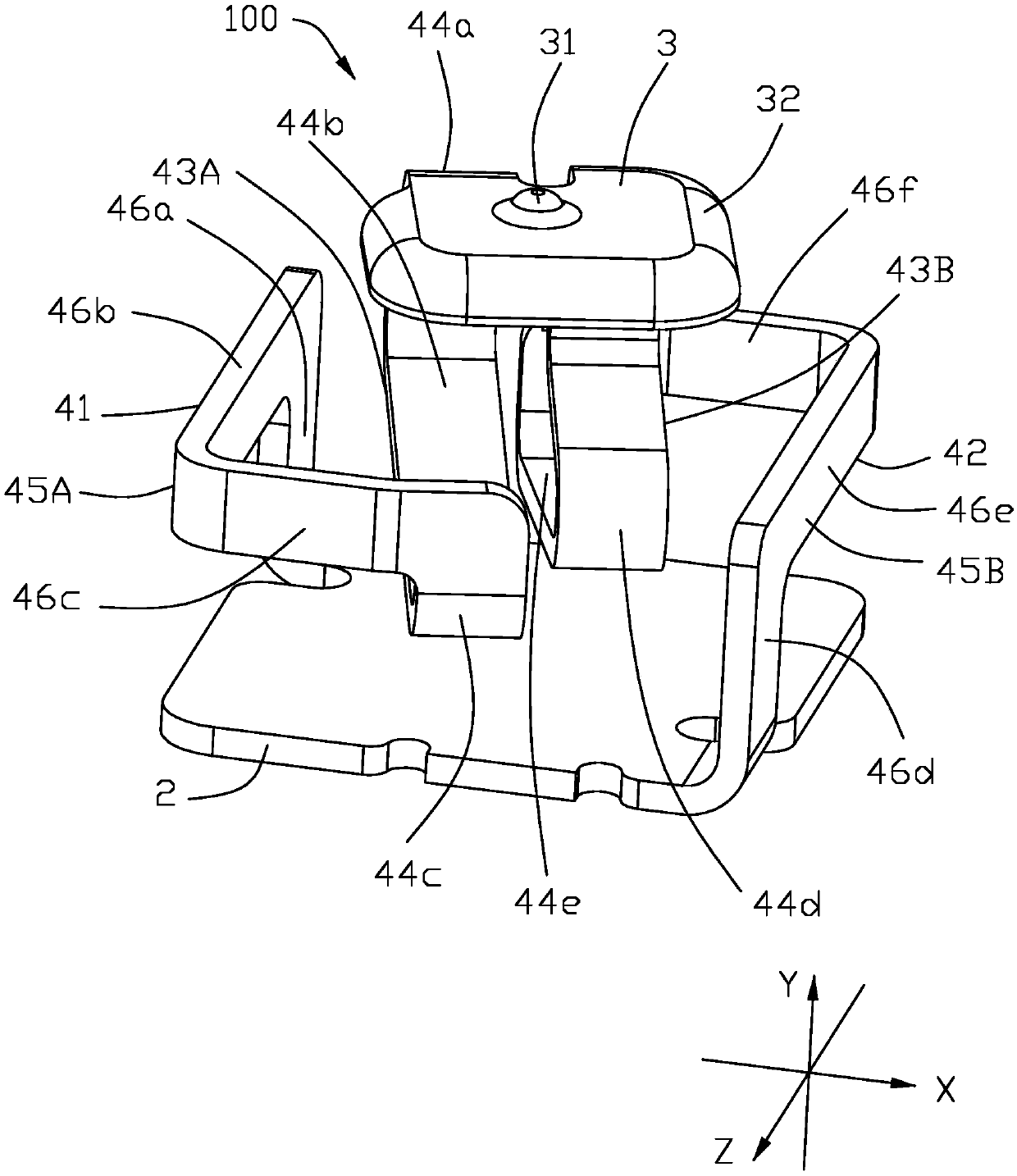
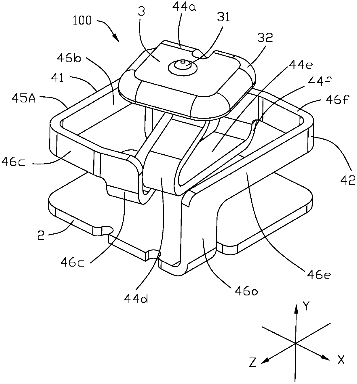
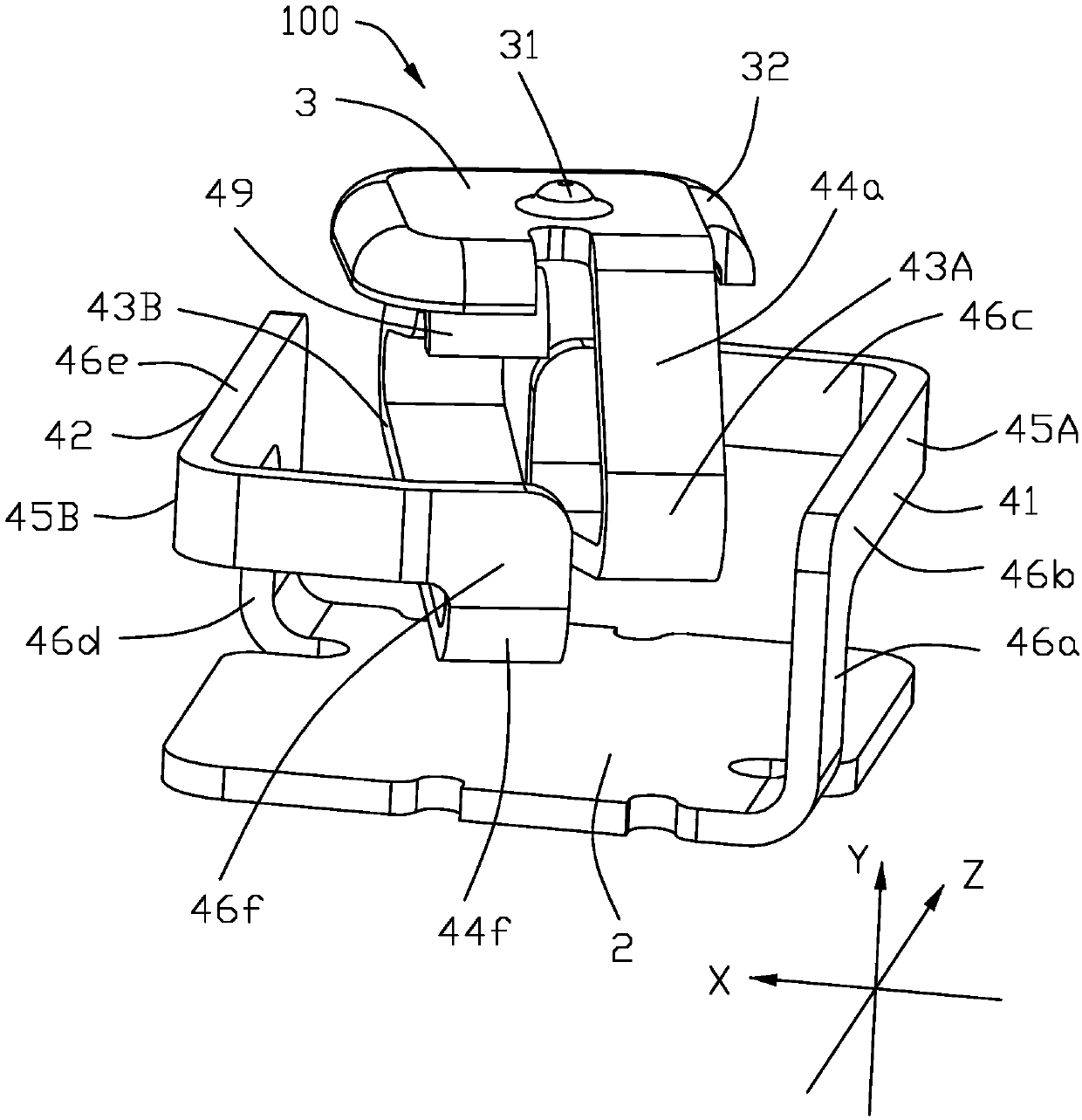
[0047] Below, will combine Figure 1 to Figure 1 4. Introduce the specific implementation of the crimp connector 100 of the present invention. The direction definitions involved in the description of the present invention are all based on figure 1 As a reference, define the pressing plate 3 of the crimping connector 100 for crimping with the butt connector (not shown) as the upper end, that is, the crimping direction is the up-down direction; the horizontal direction perpendicular to the up-down direction, that is, the left-right direction direction; and a front-rear direction perpendicular to the up-down direction and the lateral direction. exist Figure 1 to Figure 1 In 4, the X-axis indicates the left-right direction, and the direction indicated by the arrow of the X-axis is left; the Y-axis indicates the up-down direction, and the direction indicated by the arrow of the Y-axis is upward; ahead.

[0048] Please refer to Figure 1 to Figure 7As shown, the present invent...


PUM


Abstract

The invention provides a crimping connector. The crimping connector comprises a substrate, a press plate and two elastic parts, wherein the press plate is arranged on the substrate, the two elastic parts are arranged between the substrate and the press plate and are formed by continuously bending, the two elastic parts are arranged below the press plate at intervals, the two elastic parts has elasticity in a vertical direction so that the press plate elastically moves along the vertical direction, pressure borne by the press plate can be uniformly allocated to the two elastic parts, balanced elastic support can be given to the press plate by the two elastic parts, the press plate is enabled to stably move downwards, and longer service lifetime of the two elastic parts is also ensured; andsince the two elastic parts are not overlapped in the vertical direction, the two elastic parts cannot be intervened by each other during the vertical elastic deformation process, the bending step ofthe elastic parts is simple during manufacturing, and the crimping connector is easy to manufacture.

Description

[0001] 【Technical field】 [0002] The invention relates to a crimping connector, in particular to a crimping connector and a manufacturing method thereof. [0003] 【Background technique】 [0004] Referring to the invention patent No. CN105098432A disclosed in China, it discloses a crimping connector, a first spring part is connected between the upper flat part and the lower flat part, and a spring extending from the lower flat part is located on the upper side. The bottom of the flat part is used to support the second spring part of the upper side flat part. Since the widths of the first spring part and the second spring part in the lateral direction are greater than their thicknesses in the up-down direction, that is, they are all vertically arranged structures, so that the stress at the position of the base of each spring part is relatively large, It is easy to have a surrender state, which affects the stability of the rebound height. Furthermore, since the two spring parts...

Claims


Application Information

Patent Timeline
Patent Type & Authority Applications(China)
IPC IPC(8): H01R13/24H01R43/16
CPCH01R13/2428H01R43/16
Inventor 曾威达
Owner FOXCONN (KUNSHAN) COMPUTER CONNECTOR CO LTD
Why Eureka
Try Eureka