Signal sending method and device, signal receiving method and device, storage medium and electronic device

A sending method and technology of sending method, applied in the field of communication, can solve problems such as low resource utilization, no solution found, inflexibility, etc., to achieve the effect of improving resource utilization and improving sending flexibility

Active Publication Date: 2019-07-26
ZTE CORP
View PDF6 Cites 0 Cited by
  • Summary
  • Abstract
  • Description
  • Claims
  • Application Information

AI Technical Summary

Problems solved by technology

The main problem with related technologies is that the transmission strategy is determined entirely according to the type of channel or signal, which is not flexible, and the resource utilization rate is still not high
[0005] For example: conflicts between potential control regions and some reference signals, such as figure 1 as shown, figure 1 It is a schematic diagram of signal conflict in the related technology of the present invention. In the control area CORESET configured by the terminal, no matter whether there is downlink control signaling (Downlink control signaling, DCI) sent, it cannot be used for channel state information reference signal (Channel state information reference signal, CSI-RS), and tracking reference signal TRS and other types of reference signals, resulting in waste of resources
[0006] In the uplink, although the conflict between the uplink sounding reference signal SRS and the uplink Physical uplink control channel (PUCCH) is not the same as that in the downlink, the essence of the problem is the same, and resources will be wasted
[0007] For the above-mentioned problems existing in related technologies, no effective solution has been found yet

Method used


Image

  • Signal sending method and device, signal receiving method and device, storage medium and electronic device
  • Signal sending method and device, signal receiving method and device, storage medium and electronic device
  • Signal sending method and device, signal receiving method and device, storage medium and electronic device

Examples


Embodiment 1

[0026] The network architecture in which the embodiments of the present application can operate includes: a sending end and a receiving end, where the sending end and the receiving end perform signal interaction.

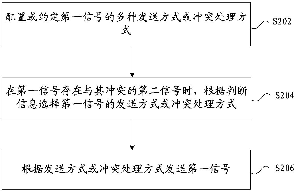
[0027] In this embodiment, a method for sending signals running on the above-mentioned network architecture is provided, figure 2 is a flow chart of a signal sending method according to an embodiment of the present invention, such as figure 2 As shown, the process includes the following steps:

[0028] Step S202, configuring or agreeing on multiple transmission modes or conflict handling modes of the first signal;

[0029] Step S204, when there is a second signal that conflicts with the first signal, select a transmission mode or a conflict handling mode for the first signal according to the judgment information;

[0030] Step S206, sending the first signal according to the sending manner or the conflict handling manner.

[0031] Through the above steps, when t...

Embodiment 2

[0064] In this embodiment, a sending and receiving device is also provided, and the device is used to implement the above-mentioned embodiments and preferred implementation modes, and what has already been described will not be repeated. As used below, the term "module" may be a combination of software and / or hardware that realizes a predetermined function. Although the devices described in the following embodiments are preferably implemented in software, implementations in hardware, or a combination of software and hardware are also possible and contemplated.

[0065] Figure 4 is a structural block diagram of a signal sending device according to an embodiment of the present invention, such as Figure 4 As shown, the device includes:

[0066] A preprocessing module 40, configured to configure or agree on multiple transmission modes or conflict handling modes of the first signal;

[0067] A selection module 42, configured to select a transmission mode or a conflict handling...

Embodiment 3

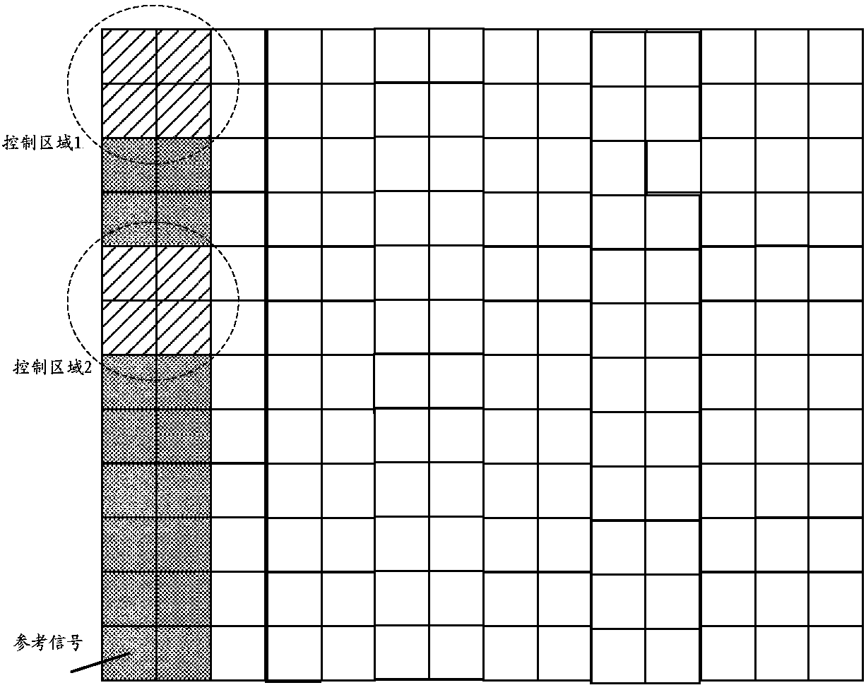
[0075] The solution of this embodiment includes two aspects, a signal sending method and a receiving method. The configuration of the control area allows one or more, and the discrete control area may occupy more frequency domain resources and support the sharing of multiple users. However, whether there is DCI being sent in the control area of ​​each time slot, and whether it is fully occupied are all dynamically changed. The transmission of the reference signal should be allowed in the case of no occupation, or in the case of some available resources in the control area. Image 6 It is a schematic diagram of signal transmission and signal reception in this embodiment.

[0076] The method of sending the signal, including:

[0077] Step 101: The transmitting end configures or transmits multiple transmission modes of the agreed signal at the receiving end;

[0078] Further, the various sending modes include a conflict handling mode when colliding with other signals.

[0079...


PUM


Abstract

The invention provides a signal sending method and device, a signal receiving method and device, a storage medium and an electronic device, and the signal sending method comprises the steps: configuring or appointing a plurality of sending modes or conflict processing modes of a first signal; when the first signal has a second signal conflicting with the first signal, selecting a sending mode or aconflict processing mode of the first signal according to the judgment information; and sending the first signal according to the sending mode or the conflict processing mode. Through the method andthe device, the technical problem that the resource utilization rate is too low when conflicting signals are sent in the prior art is solved, and the sending flexibility during signal conflicting is improved, so that the resource utilization rate is improved.

Description

technical field [0001] The present invention relates to the communication field, in particular, to a method and device for sending and receiving signals, a storage medium, and an electronic device. Background technique [0002] In the related art, there are various reference signals (reference signals) in 5G (New Radio, NR), which can also be generally called pilots, and these pilots have their own functions. Downlink pilot: including DL DMRS (downlink demodulation reference signal), CSI-RS (channel state information reference signal), DL PTRS (downlink phase tracking reference signal), TRS (timing reference signal); the main function of DL DMRS is to use For downlink data demodulation, DL PTRS is mainly used for downlink phase noise estimation and performance improvement. There are several types of CSI-RS: CSI-RS used for beam management; CSI-RS used for CSI measurement of downlink channels. TRS is mainly used for time-frequency offset tracking. Uplink pilot: including U...

Claims


Application Information

Patent Timeline
Patent Type & Authority Applications(China)
IPC IPC(8): H04L5/00
CPCH04L5/0048H04L27/261H04L5/0051H04L5/0062H04L5/0053H04L5/10H04W72/0446H04W72/0453
Inventor 陈艺戬鲁照华卢忱
Owner ZTE CORP
Why Eureka
Try Eureka