
Method for defining static high-definition image shooting area in dynamic image preview

A technology of dynamic images and high-definition images, applied in the field of image processing, can solve the problems of unclear intercepted images, cumbersome operations, and inability to obtain high-definition images of original high-definition images, and achieves the effects of strong practicability, high definition and simple operation.

Active Publication Date: 2019-07-26
CHENGDU YINENG SCI&TECH CO LTD
View PDF6 Cites 3 Cited by
  • Summary
  • Abstract
  • Description
  • Claims
  • Application Information

AI Technical Summary

Problems solved by technology

[0005] The purpose of the present invention is to provide a method for defining the static high-definition image shooting area under the dynamic image preview, to solve the problem that the intercepted image in the existing image interception method is not clear, the original high-definition image cannot be obtained or the intercepted high-definition image is an overall picture, Second cropping is required, and the operation is cumbersome

Method used


Image

  • Method for defining static high-definition image shooting area in dynamic image preview

Examples


Embodiment 1

[0057] The teacher needs to explain the test paper during class, and only needs to obtain the part of the test question, and the rest of the content is not needed. The steps to obtain the test question image are as follows:

[0058] Step 1. Use the high-speed camera to preview and shoot the content of the test paper, and display the content of the test paper captured in the preview mode on the computer display screen in real time.

[0059] Step 2, calculate the width ratio or height ratio of the dynamic image on the computer display screen and the dynamic original image of the Gaopai instrument;

[0060] Specific steps are as follows:

[0061] Step 201. Obtain the width and height of the original dynamic image of the high-speed camera. Here, the width and height of the original dynamic image are obtained through the resolution of the Gaopai instrument, and the width*height of the original dynamic image of the Gaopai instrument is preset to 4032*3016;

[0062] Step 202, obtai...

Embodiment 2

[0081] During the experimental demonstration, it is necessary to save the image of the equipment and operation method of the experimental demonstration, and the rest of the operating environment and background are not required. The image acquisition steps are as follows:

[0082] Step 1. Shoot the experimental demonstration process through the camera, and display the dynamic image content captured in the preview mode on the computer display screen in real time.

[0083] Step 2, calculating the width ratio or height ratio of the dynamic image of the computer display screen and the original dynamic image of the camera;

[0084] Specific steps are as follows:

[0085] Step 201, acquiring the width and height of the original dynamic image of the camera. Here, the original dynamic image size is obtained through the camera resolution, for example, the original dynamic image size of the camera is 4032*3016;

[0086] Step 202, obtaining the display height and width of the dynamic im...


PUM


Abstract

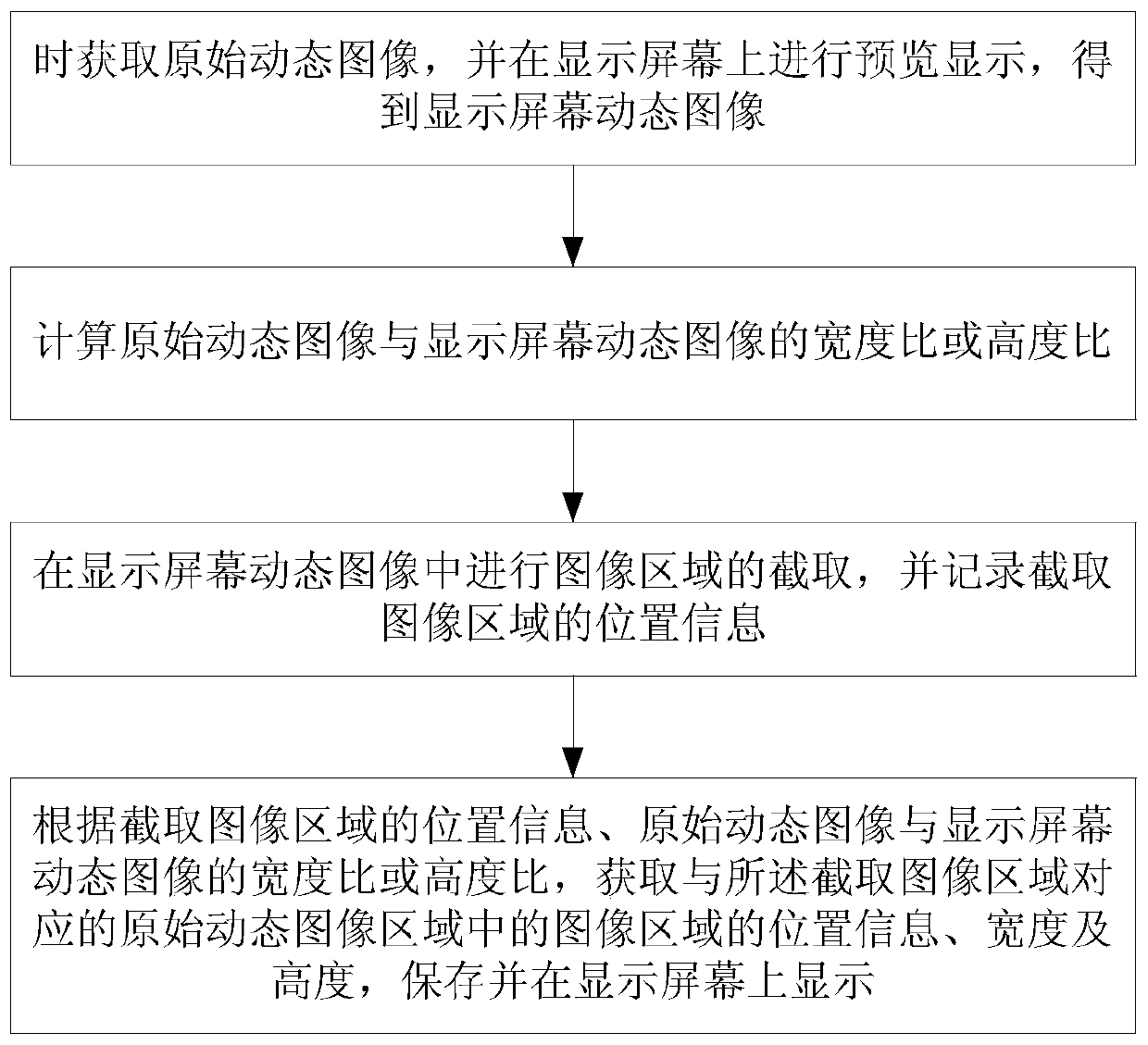
The invention provides a method for defining a static high-definition image shooting area in dynamic image preview, and belongs to the field of image processing. The method solves the problems that inan existing image interception mode, an intercepted image is not clear, an original high-definition image cannot be obtained or the intercepted high-definition image is an overall picture, secondaryclipping is needed, and operation is complex. According to the technical scheme, the method comprises: obtaining an original dynamic image in real time and previewed and displayed on a display screen,and obtaining a display screen dynamic image; calculating a width ratio or a height ratio of the original dynamic image to the display screen dynamic image; intercepting an image area in the dynamicimage of the display screen, and recording the position information of the intercepted image area; and acquiring position information, width and height of an image region in the original dynamic imageregion corresponding to the captured image region according to the position information of the captured image region and the width ratio or height ratio of the original dynamic image to the dynamic image of the display screen, and storing and displaying the position information, width and height of the image region on the display screen.

Description

technical field [0001] The invention relates to image processing technology, in particular to the technology of a method for defining a static high-definition image shooting area under dynamic image preview. Background technique [0002] At present, with the popularization and application of information-based teaching equipment, the traditional "blackboard + chalk" classroom teaching is gradually being upgraded to multimedia-assisted teaching based on computer networks, large-screen display equipment, and voice systems. In order to further promote the application of information-based teaching in schools and improve the teaching level and efficiency, more and more schools have introduced display systems for teaching materials, such as: experimental demonstrations, test paper explanations, example explanations, etc. [0003] Real-time shooting of real objects and various printing materials by camera equipment, and synchronously displaying and explaining on the large screen, bu...

Claims


Application Information

Patent Timeline
Patent Type & Authority Applications(China)
IPC IPC(8): H04N5/232
CPCH04N23/80
Inventor 罗辉刘鑫庞炜陈挚黄启挺
Owner CHENGDU YINENG SCI&TECH CO LTD
Learn More