Sealing ring take-out device

A technology of a material retrieving device and a sealing ring, which is applied in metal processing, metal processing equipment, manufacturing tools, etc., and can solve problems such as twisting of the sealing ring 10 and reducing the sealing performance of the sealing ring 10

Active Publication Date: 2019-07-30
泰州镭昇光电科技有限公司
View PDF7 Cites 4 Cited by
  • Summary
  • Abstract
  • Description
  • Claims
  • Application Information

AI Technical Summary

Problems solved by technology

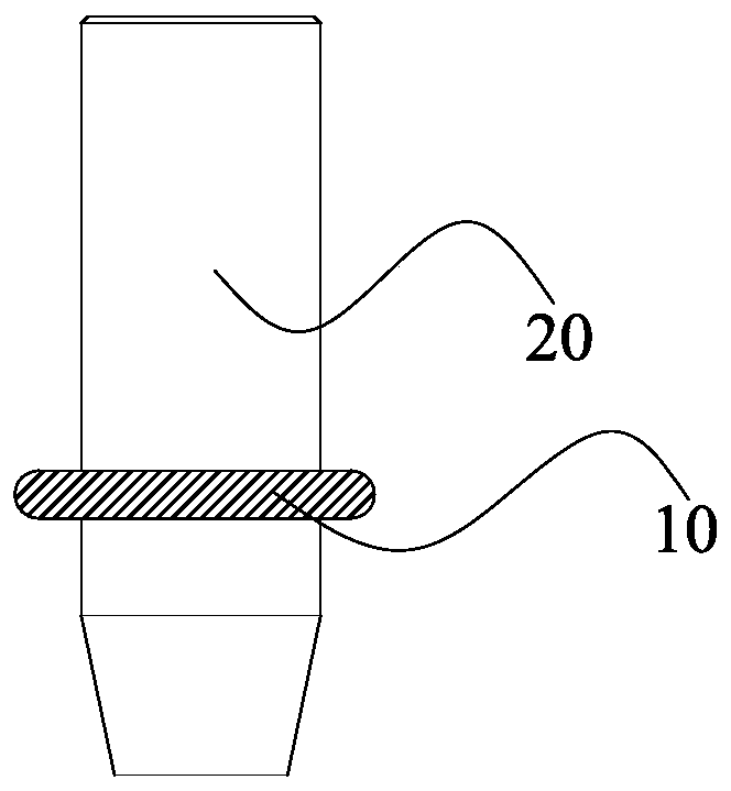
[0003] However, due to the good elasticity of the sealing ring 10, when the cylindrical rod 20 is inserted into the inner ring of the sealing ring 10, friction will be generated between the inner ring of the sealing ring 10 and the outer wall of the cylindrical rod 20, so the elastic sealing Circle 10 is highly likely to be distorted (eg image 3 As shown), the twisted sealing ring 10 has changed its original shape. It can be seen that when the twisted sealing ring 10 is socketed on other parts, the sealing performance of the sealing ring 10 will be reduced.

Method used


Image

  • Sealing ring take-out device
  • Sealing ring take-out device
  • Sealing ring take-out device

Examples


Embodiment Construction

[0035] In order to facilitate the understanding of the present invention, the present invention will be described more fully below with reference to the associated drawings. Preferred embodiments of the invention are shown in the accompanying drawings. However, the present invention can be embodied in many different forms and is not limited to the embodiments described herein. On the contrary, the purpose of providing these embodiments is to make the disclosure of the present invention more thorough and comprehensive.

[0036] It should be noted that when an element is referred to as being “fixed” to another element, it can be directly on the other element or there can also be an intervening element. When an element is referred to as being "connected to" another element, it can be directly connected to the other element or intervening elements may also be present. The terms "vertical," "horizontal," "left," "right," and similar expressions are used herein for purposes of ill...


PUM


Abstract

The invention discloses a sealing ring take-out device. The sealing ring take-out device comprises a sealing ring in-place mechanism and a sealing ring take-out mechanism, wherein the sealing ring in-place mechanism comprises an in-place pedestal and a floating assembly; a take-in slot is formed in the in-place pedestal; a passing hole is formed in the slot wall of the take-in slot; a plurality ofsealing ring supporting blocks are arranged on the hole wall of the passing hole; the floating assembly comprises a floating lifting rod and a floating elastic part; one end, in the take-in slot, ofthe floating lifting rod is equipped with a sealing ring positioning blocking block; the sealing ring positioning blocking block is provided with a sealing ring charge slot and a sealing ring blockingslot; and the sealing ring take-out mechanism comprises a lifting translation assembly, a lifting translation sleeve, a splicing drive part, a movable splicing rod and a plurality of fixed pressing-holding blocks. The sealing ring take-out device enables a sealing ring to be free of twisting deformation in a process of taking out the sealing ring.

Description

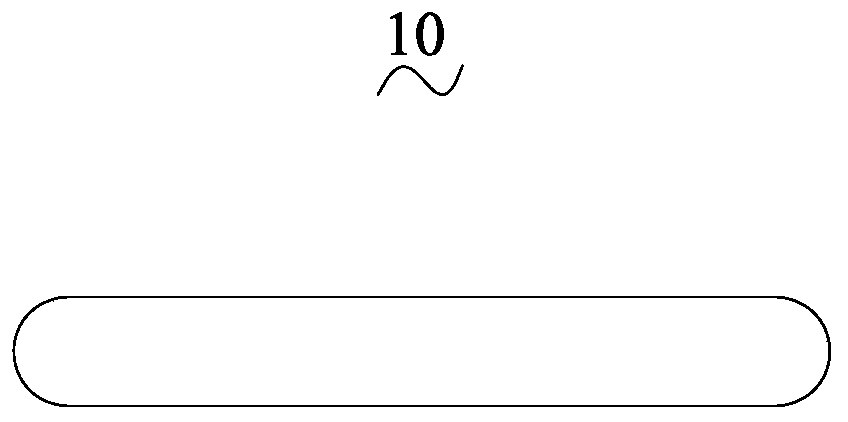
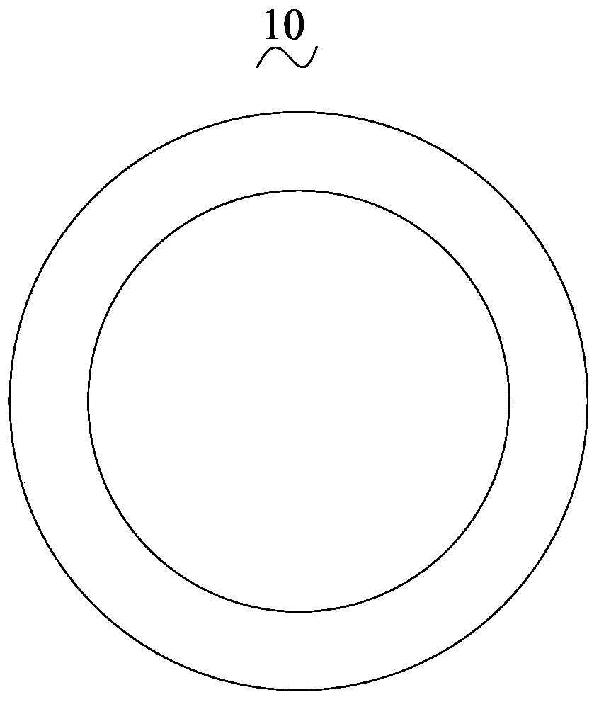
technical field [0001] The invention relates to the technical field of mechanical automation, in particular to a sealing ring retrieving device. Background technique [0002] Such as figure 1 and figure 2 As shown, it is a structural diagram of a sealing ring 10, and the sealing ring 10 is in the shape of a ring. In order to better improve the mechanical automation level of the enterprise, mechanical automation equipment is usually developed and designed to reclaim the sealing ring 10, thereby replacing traditional manual labor. For example, in the process of design and development, the usual practice in the industry is to design a cylindrical rod 20 (such as image 3 As shown), since the sealing ring 10 has good elasticity, by inserting the cylindrical rod 20 into the inner ring of the sealing ring 10, the sealing ring 10 will elastically deform and expand, so that the sealing ring 10 will It is firmly socketed on the outer wall of the cylindrical rod 20, thereby reali...

Claims


Application Information

Patent Timeline
Patent Type & Authority Applications(China)
IPC IPC(8): B23P19/04
CPCB23P19/04
Inventor 不公告发明人
Owner 泰州镭昇光电科技有限公司
Why Eureka
Try Eureka