
Conveying belt

A conveyor belt and core technology, which is applied in the field of conveyor belts, can solve problems such as accelerating the replacement process of conveyor belts and breaking the antistatic layer

Pending Publication Date: 2019-07-30
南京东润带业有限公司
View PDF0 Cites 1 Cited by
  • Summary
  • Abstract
  • Description
  • Claims
  • Application Information

AI Technical Summary

Problems solved by technology

[0002] The existing antistatic conveyor belt production process needs to coat the special antistatic slurry on the fabric; however, the surface layer formed by the slurry is different from the force deformation of the fabric layer during the final use of the conveyor belt. The antistatic layer is broken, which speeds up the replacement process of the conveyor belt; especially when the conveyor belt has a large conveying load and steel cords are installed inside the conveyor belt, this problem is more obvious

Method used


Image

  • Conveying belt
  • Conveying belt

Examples


Embodiment Construction

[0014] The present invention will be further described below in conjunction with accompanying drawing of description and embodiment:

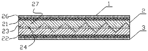
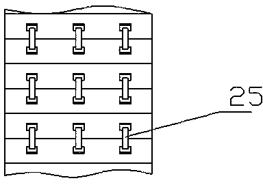
[0015] A kind of conveyer belt as shown in the figure, comprises: glue layer 1, core body layer 2 and primer layer 3 connected successively, and described core body layer comprises upper core body layer 21, lower core body layer 22 and several steel Cord 23, the lower side of the upper core layer and the upper side of the lower core layer are in a wavy shape interlocking; the peaks of the lower side of the upper core layer and the peaks of the upper side of the lower core layer are respectively Correspondingly, several steel cord grooves 25 are provided, so that steel cord tunnels are formed inside the core layer, and the steel cords are located in the steel cord tunnels; sheet 24, and the limiting sheets are located at the connection seam between the upper core layer and the lower core layer.

[0016] By setting the core layer as an upper cor...


PUM


Abstract

The invention relates to a conveying belt. The conveying belt comprises an upper glue layer, a core layer and a primer layer which are connected in sequence. The core layer comprises an upper core layer body, a lower core layer body and a plurality of steel cords. The lower side face of the upper core layer body and the upper side face of the lower core layer body are in the shape of engaged waves. A plurality of steel cord grooves are correspondingly formed in wave crests on the lower side face of the upper core layer body and wave crests on the upper side face of the lower core layer body respectively. Therefore, a steel cord pore passage is formed in the core layer, and the steel cords are located in the steel cord pore passage. Besides, a plurality of limiting sheets are fixedly arranged on the steel cords, the limiting sheets are located on joints between the upper core layer body and the lower core layer body. The core layer is arranged into the upper core layer body and the lower core layer body with wavy faces, so that the deformation of the steel cords is limited by the wavy faces when bearing loads, and the upper glue layer and the primer layer on the surface of the conveying belt are prevented from stress breakage.

Description

technical field [0001] The invention relates to a conveyor belt. Background technique [0002] The existing antistatic conveyor belt production process needs to coat the special antistatic slurry on the fabric; however, the surface layer formed by the slurry is different from the force deformation of the fabric layer during the final use of the conveyor belt. The antistatic layer is broken, which speeds up the replacement process of the conveyor belt; especially when the conveyor belt has a large conveying load and steel cords are installed inside the conveyor belt, this problem is more obvious. Contents of the invention [0003] The purpose of the present invention is to solve the above problems, and a conveyor belt is provided, which is specifically realized by the following technical solutions: [0004] A conveyor belt, comprising: an upper glue layer, a core layer and a primer layer connected in sequence, the core layer includes an upper core layer, a lower core layer...

Claims


Application Information

Patent Timeline
Patent Type & Authority Applications(China)
IPC IPC(8): B32B3/08B32B3/24B32B3/28B32B5/02B32B7/12B32B25/10B32B33/00B65G15/36
CPCB32B3/28B32B3/085B32B3/266B32B7/12B32B25/10B32B5/02B32B33/00B65G15/36B32B2255/02B32B2255/26B32B2250/40B32B2307/21B32B2307/554B32B2433/02
Inventor 江文养江文军江琳夏三华
Owner 南京东润带业有限公司
Learn More