
Guide rail and valve seat insert structure for slide valve and slide valve

A technology of valve seat ring and guide rail, which is applied in the direction of sliding valves, valve devices, engine components, etc., can solve problems such as guide rail bolt breakage, achieve the effects of prolonging service life, avoiding force fracture, and improving safety and reliability

Inactive Publication Date: 2016-06-29
BC P INC CHINA NAT PETROLEUM CORP +1
View PDF7 Cites 0 Cited by
  • Summary
  • Abstract
  • Description
  • Claims
  • Application Information

AI Technical Summary

Problems solved by technology

[0005] In order to solve the problem that the existing technology cannot fundamentally avoid the breakage of the guide rail bolts in the high temperature zone of the slide valve for catalytic cracking, the embodiment of the present invention provides a guide rail for the slide valve, a valve seat ring structure and a slide valve

Method used


Image

  • Guide rail and valve seat insert structure for slide valve and slide valve

Examples


Embodiment 1

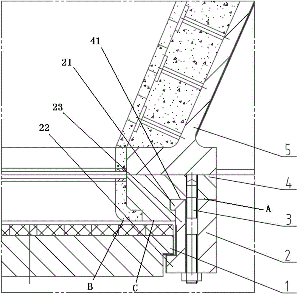
[0029] Such as figure 1 As shown, the present invention provides a guide rail and seat ring structure for a slide valve. The slide valve includes a throttling cone 5 and a T-shaped valve plate 1. The guide rail and seat ring structure for a slide valve include: a valve seat Ring 4, U-shaped guide rail 2 and guide rail bolts 3, the valve seat ring 4 is fixedly connected to the bottom of the throttle cone 5, the valve seat ring 4 and the U-shaped guide rail 2 form a snap-fit ​​connection, the The T-shaped valve plate 1 is set in the U-shaped guide rail 2, the guide rail bolt 3 passes through the U-shaped guide rail 2 and extends into the valve seat ring 4, and the U-shaped valve plate is fixed by the guide rail bolt 3 The guide rail 2 and the valve seat ring 4, the throttle cone 5, the slide valve guide rail, the structure of the valve seat ring 4 and the T-shaped valve plate 1 are assembled as a whole.

[0030] The valve seat ring 4 forms a snap-fit ​​connection with the U-sha...

Embodiment 2

[0041] see figure 1 , the present invention provides a spool valve, the spool valve comprises a throttling cone 5, a guide rail for the spool valve, a valve seat ring structure and a T-shaped valve plate 1 from top to bottom, the guide rail for the spool valve, the valve seat The ring structure includes: valve seat ring 4, U-shaped guide rail 2 and guide rail bolts 3, the valve seat ring 4 is fixedly connected to the bottom of the throttle cone 5, and the valve seat ring 4 and the U-shaped guide rail 2 form a buckle The T-shaped valve plate 1 is set in the U-shaped guide rail 2, the guide rail bolts 3 pass through the U-shaped guide rail 2 and extend into the valve seat ring 4, and pass through the guide rail bolts 3 Fixing the U-shaped guide rail 2 and the valve seat ring 4, the throttle cone 5, the slide valve guide rail, the seat ring structure and the T-shaped valve plate 1 are assembled as a whole.

[0042] The present invention provides and changes the structure of the ...


PUM


Abstract

The invention discloses a slide valve guide rail, a valve seat ring structure and a slide valve, which belong to the field of petrochemical industry. The slide valve includes a throttling cone and a T-shaped valve plate. The guide rail and seat ring structure for the slide valve includes a U-shaped guide rail, a seat ring and a guide rail bolt. The seat ring is fixedly connected to the bottom of the throttle cone. The seat ring and the U-shaped The guide rail forms a snap-fit ​​connection, the T-shaped valve plate is set in the U-shaped guide rail, and the U-shaped guide rail and the seat ring, the throttle cone, the slide valve guide rail, the valve seat ring structure and the T-shaped valve plate are fixed by the guide rail bolts Assembled as a whole. Through the above structure, the U-shaped guide rail bears all the working tensile stress, and the guide rail bolts mainly play a positioning role rather than a load-bearing element, which realizes the force transfer of the guide rail bolts, fundamentally avoids the problem of guide rail bolts being broken by force, and increases the slide valve. The reliability of the connection of internal main parts improves the safety and reliability of the slide valve and prolongs the service life of the whole machine.

Description

technical field [0001] The invention relates to the field of petrochemical industry, in particular to a slide valve guide rail, a valve seat ring structure and a slide valve. Background technique [0002] The catalytic cracking slide valve is mainly used in the catalyst circulation pipeline or the flue gas pipeline, and the passing medium is high-temperature catalyst or high-temperature flue gas with catalyst particles. Due to the special use position, complex media and harsh working environment, the main components inside the catalytic cracking slide valve are easily damaged, which often poses a safety hazard to the operation of the device. In order to ensure the safe and reliable operation of the catalytic cracking unit, major professional design institutes at home and abroad have designed various slide valve guide rails and valve seat ring structures. [0003] Based on the design concept of high temperature resistance and erosion resistance, at present, there are mainly ...

Claims


Application Information

Patent Timeline
Patent Type & Authority Applications(China)
IPC IPC(8): F16K3/314F16K3/30
Inventor 张玉峰路登明
Owner BC P INC CHINA NAT PETROLEUM CORP
Learn More