A Synthetic Aperture LiDAR Imaging Method, Instrument and System

A synthetic aperture laser and radar imaging technology, applied in instruments, radio wave measurement systems, measurement devices, etc., can solve problems such as difficult to achieve SAL high-resolution imaging, severe image defocus, and difficult to achieve image focus

Active Publication Date: 2021-10-29
INST OF ELECTRONICS CHINESE ACAD OF SCI
View PDF14 Cites 0 Cited by
  • Summary
  • Abstract
  • Description
  • Claims
  • Application Information

AI Technical Summary

Problems solved by technology

However, the following two traditional motion compensation ideas are also difficult to solve the problem of sub-micron SAL motion error compensation: First, the motion compensation method based on the motion measurement sensor is realized by a high-precision positioning and orientation system (Position and Orientation System, POS) Measurement of platform vibration, motion error compensation during imaging processing
However, the position measurement accuracy of the current highest-precision POS system is on the order of centimeters, which is far from meeting the needs of SAL high-resolution imaging; secondly, the most classic method of motion estimation and compensation based on radar echo data is the phase gradient self-focusing algorithm
This method relies on the existence of certain strong scattering points in the current area, and it will be difficult to achieve image focus for uniform scenes without ideal point targets.
And because the laser wavelength is extremely short, the negligible motion error in the traditional microwave band will cause a phase error of more than 2π, and the image defocus is very serious, which brings great challenges to the phase gradient self-focusing algorithm

Method used


Image

  • A Synthetic Aperture LiDAR Imaging Method, Instrument and System
  • A Synthetic Aperture LiDAR Imaging Method, Instrument and System
  • A Synthetic Aperture LiDAR Imaging Method, Instrument and System

Examples


Embodiment Construction

[0040] Hereinafter, embodiments of the present invention will be described with reference to the drawings. It should be understood, however, that these descriptions are exemplary only and are not intended to limit the scope of the present invention. In the following detailed description, for purposes of explanation, numerous specific details are set forth in order to provide a thorough understanding of the embodiments of the invention. It may be evident, however, that one or more embodiments may be practiced without these specific details. Also, in the following description, descriptions of well-known structures and techniques are omitted to avoid unnecessarily obscuring the concept of the present invention.

[0041] The terminology used herein is for the purpose of describing particular embodiments only, and is not intended to be limiting of the invention. The terms "comprising", "comprising", etc. used herein indicate the presence of stated features, steps, operations and / ...


PUM


Abstract

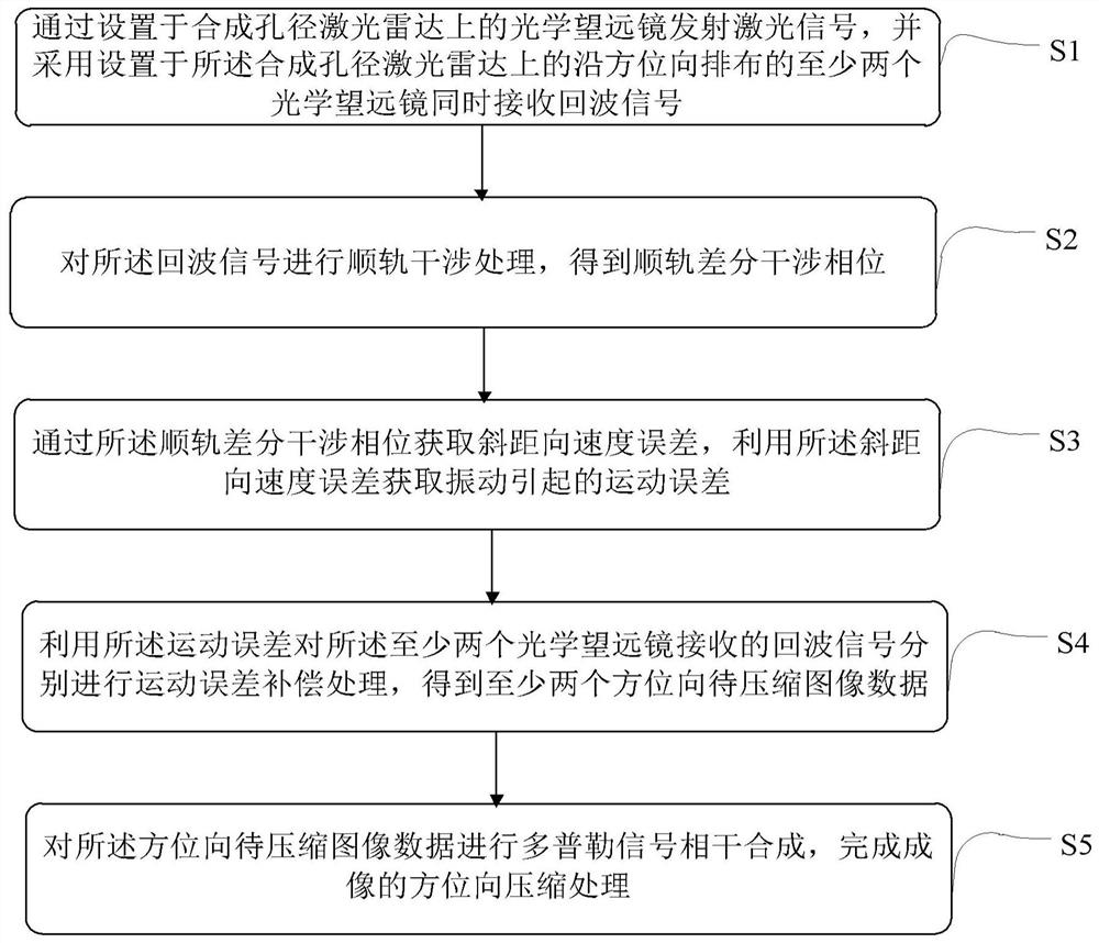
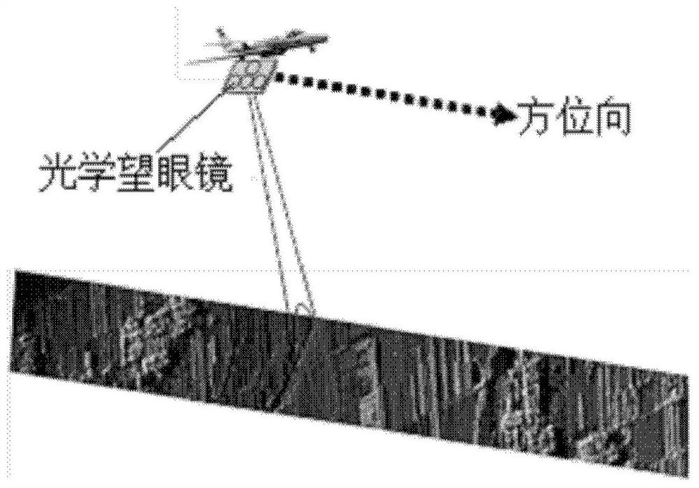
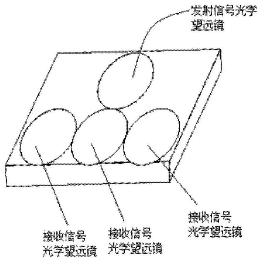
The invention provides a synthetic aperture laser radar imaging method, instrument and system. The method includes: transmitting laser signals through an optical telescope arranged on the synthetic aperture lidar, and simultaneously receiving echo signals by using at least two optical telescopes arranged on the synthetic aperture lidar along the azimuth direction; The echo signal is subjected to along-track interference processing to obtain the along-track differential interferometric phase; the slant-range velocity error is obtained through the along-track differential interferometric phase, and the motion error caused by vibration is obtained by using the slant-range velocity error; The above motion error performs motion error compensation processing on the echo signals received by the at least two optical telescopes to obtain at least two azimuth image data to be compressed; perform Doppler signal coherent synthesis on the azimuth image data to be compressed , to complete the azimuth compression processing of the imaging.

Description

technical field [0001] The invention relates to a synthetic aperture laser radar imaging method, instrument and system. Background technique [0002] Synthetic Aperture Lidar (SAL) combines synthetic aperture technology and coherent laser detection technology, and has a series of technical characteristics such as large Doppler frequency shift, high pointing accuracy, high ranging accuracy, and short synthetic aperture time. Synthetic aperture lidar solves the technical bottlenecks of LiDAR system grid density, imaging resolution and detection energy. Realize a brand-new synthetic aperture radar system based on optical band, break through the diffraction limit of geometric optics, and greatly improve the imaging resolution. The laser signal is convenient for large-bandwidth modulation, so it is beneficial to improve the range resolution; a small relative motion between the radar and the target can achieve a large azimuth Doppler shift, so it can achieve a high azimuth resolu...

Claims


Application Information

Patent Timeline
Patent Type & Authority Patents(China)
IPC IPC(8): G01S17/90G01S7/48
CPCG01S7/4802G01S17/90
Inventor 向茂生汪丙南周良将丁赤飚
Owner INST OF ELECTRONICS CHINESE ACAD OF SCI
Why Eureka
Try Eureka