
Printing cylinder of self-cleaning type printer

A technology for printing cylinders and printing machines, applied to printing machines, general parts of printing machinery, rotary printing machines, etc., can solve the problems of affecting service life, incomplete cleaning, time-consuming and labor-intensive, etc., to prolong service life and save installation time , good cleaning effect

Active Publication Date: 2019-08-02
苏州科士达印务有限公司
View PDF13 Cites 11 Cited by
  • Summary
  • Abstract
  • Description
  • Claims
  • Application Information

AI Technical Summary

Problems solved by technology

[0004] (1) When cleaning manually, tools such as brushes and scrapers are needed. Generally, scrapers are used to scrape off first, and then brushes are used to clean. The use of force is uneven and the size is different, which is easy to cause damage or scratches, poor safety, and incomplete cleaning to the outer wall of the printing cylinder caused by excessive force;
[0005] (2) When using an external independent cleaning machine to clean the outer wall of the printing cylinder, the cylinder needs to be disassembled and cleaned. The installation and disassembly are more frequent and the overall weight is heavy. service life

Method used


Image

  • Printing cylinder of self-cleaning type printer
  • Printing cylinder of self-cleaning type printer
  • Printing cylinder of self-cleaning type printer

Examples


Embodiment Construction

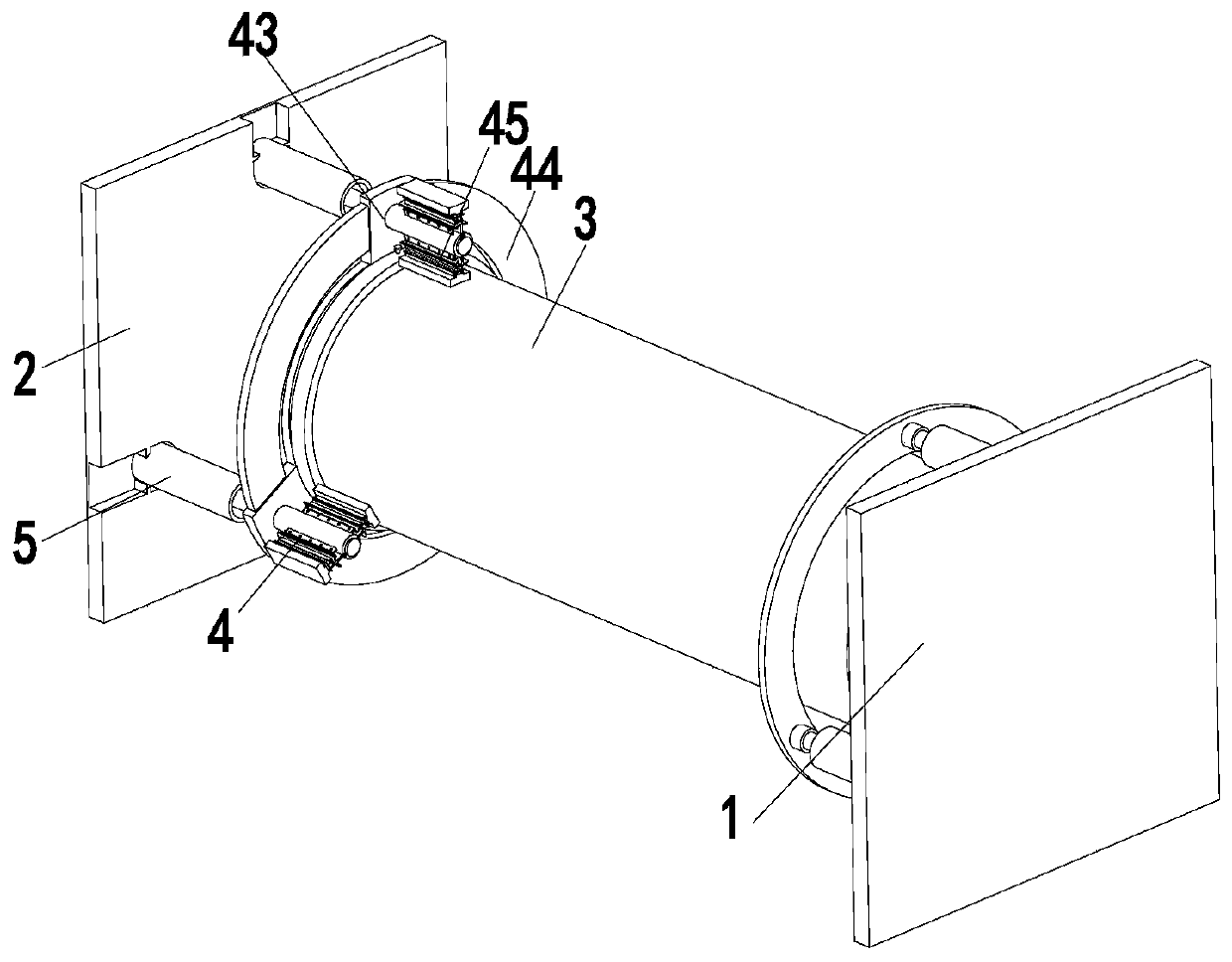
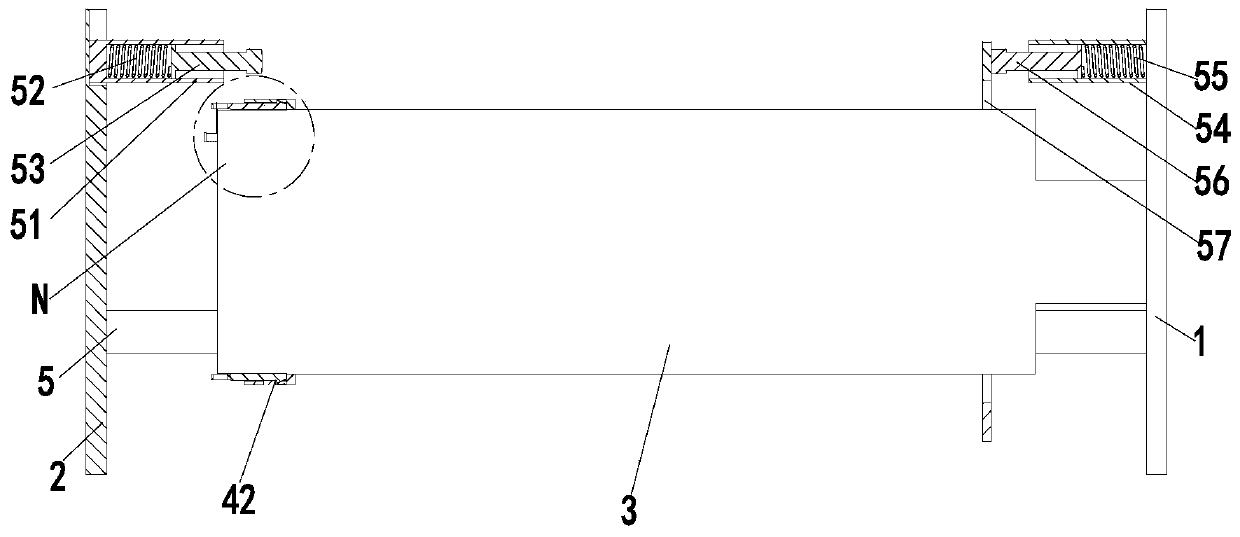
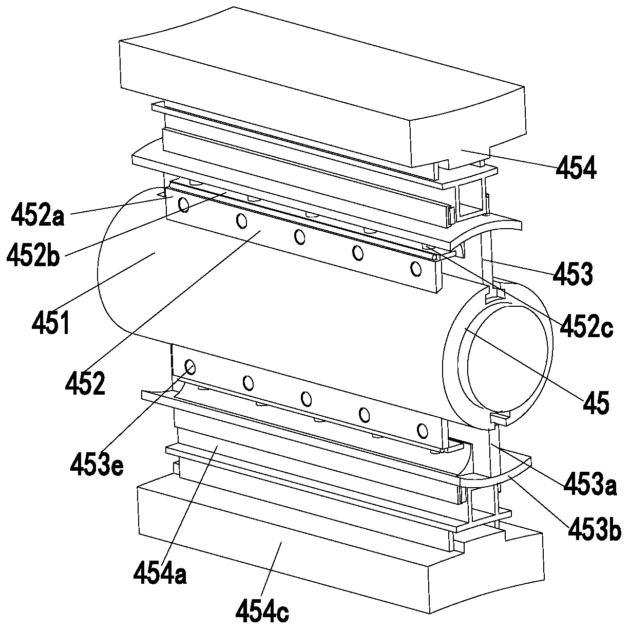
[0027] In order to make the technical means realized by the present invention, creative features, goals and effects easy to understand, the following combination Figure 1 to Figure 6 , to further elaborate the present invention.

[0028] A printing cylinder of a self-cleaning printing machine, comprising a No. 1 mounting plate 1, a No. 2 mounting plate 2, a printing cylinder body 3, a cleaning mechanism 4 and an ejection mechanism 5, and the side wall of the No. 1 mounting plate 1 is installed by a bearing There is a printing cylinder body 3, a cleaning mechanism 4 is installed on the printing cylinder body 3, and an ejection mechanism 5 is arranged at the left end of the cleaning mechanism 4, and the ejection mechanism 5 is installed on the second mounting plate 2; wherein:

[0029] The cleaning mechanism 4 includes a linear bearing 41, an installation branch chain 42, a rotating block 43, an electric turntable 44 and a cleaning branch chain 45. The upper and lower ends of t...


PUM


Abstract

The invention relates to a printing cylinder of a self-cleaning type printer. The printing cylinder of the self-cleaning type printer comprises a first installing plate, a second installing plate, a printing cylinder body, a cleaning mechanism and an ejection mechanism; the printing cylinder body is installed on the side wall of the first installing plate through a bearing, the cleaning mechanismis installed on the printing cylinder body, the ejection mechanism is arranged at the left end of the cleaning mechanism, and the ejection mechanism is installed on the second installing plate; the cleaning mechanism comprises a linear bearing, an installing branch chain, rotating blocks, an electric rotating disc and cleaning branch chains; and the ejection mechanism comprises installing cylinders, ejection springs, ejection rods, fixing cylinders, reciprocating springs, reciprocating rods and collision rings. According to the printing cylinder of the self-cleaning type printer, the printingcylinder body is detachably installed, the occupation size is small, the printing cylinder does not need to be frequently disassembled, and therefore the service life of the printing cylinder is prolonged; and stains at any positions of the outer wall of the printing cylinder can be removed instead of a manual mode, cleaning brushes can not waggle in the cleaning process, and the cleaning effect is good.

Description

technical field [0001] The invention relates to the field of printing equipment, in particular to a printing cylinder of a self-cleaning printing machine. Background technique [0002] The printing cylinder of the printing machine is the core component of the printing machine. Its surface finish and geometric accuracy will have an important impact on the quality of the printed matter. Especially when printing exquisite printed matter, the slightest error will reduce the overall effect of the printed matter. The two sides of the printed product are blurred or distorted. Because acid ink, alcohol, water and other chemical raw materials used in the printing process often adhere to the printing machine cylinder, if these stains are not dealt with in time, it will inevitably affect the quality of the printing work. And the version is different, therefore, after each single-quantity printing operation is completed, the outer surface of the cylinder needs to be cleaned to facilita...

Claims


Application Information

Patent Timeline
Patent Type & Authority Applications(China)
IPC IPC(8): B41F13/08B41F35/00
CPCB41F13/08B41F35/00
Inventor 赵妍李胜虎李亚
Owner 苏州科士达印务有限公司
Learn More