Fire source positioning method and system based on SLAM technology and image identification

A technology of image recognition and positioning method, which is applied in the direction of radio wave measurement system, electromagnetic wave reradiation, and the control of finding targets. The effect of eliminating errors

Active Publication Date: 2019-08-02
东北大学秦皇岛分校
View PDF22 Cites 15 Cited by
  • Summary
  • Abstract
  • Description
  • Claims
  • Application Information

AI Technical Summary

Problems solved by technology

[0004] The purpose of the present invention is to provide a fire source location method and system based on SLAM technology and image recognition, which can eff

Method used


Image

  • Fire source positioning method and system based on SLAM technology and image identification
  • Fire source positioning method and system based on SLAM technology and image identification
  • Fire source positioning method and system based on SLAM technology and image identification

Examples


Embodiment 1

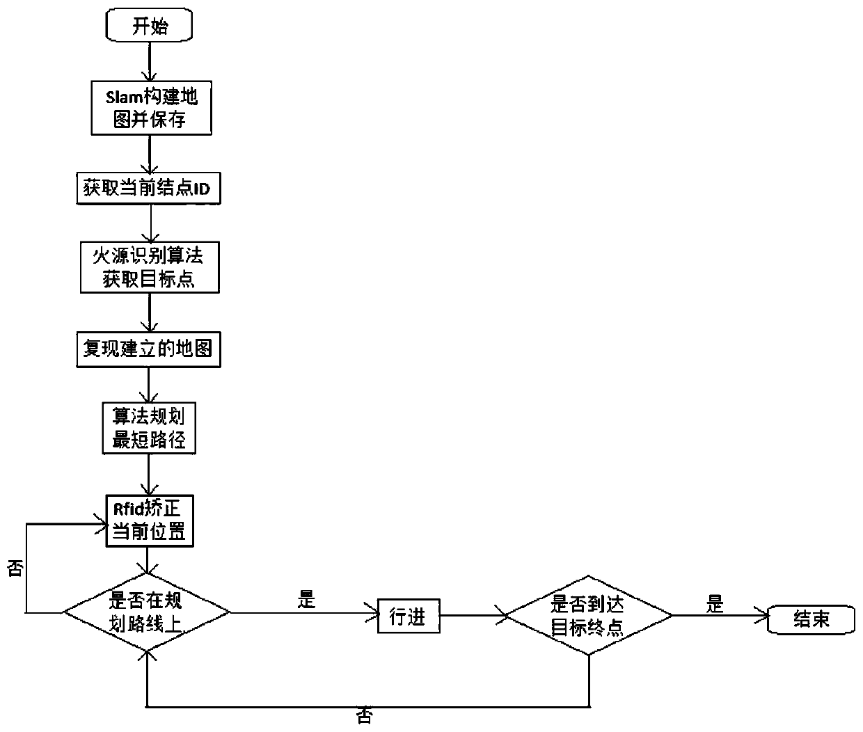
[0061] Embodiment 1 of the present invention: a kind of fire location method (can be implemented under ROS platform) based on SLAM technology and image recognition, such as image 3 shown, including the following steps:

[0062] S1. The data returned by the autonomous mobile robot through the lidar is combined with the SLAM algorithm to build a real-time map and save it; specifically, it can include: the data topic released by the autonomous mobile robot using the lidar subscribed by the ROS platform, the mileage data returned by the robot chassis, and the robot control system. After the configured coordinate relationship, the current posture of the car body and the surrounding environment information are obtained through the SLAM-GMAPPING algorithm; the host computer sends a movement command to control the robot to move accordingly, thereby creating a complete map;

[0063] S2, the robot moves autonomously based on the established real-time map, and uses the camera to capture...

Embodiment 2

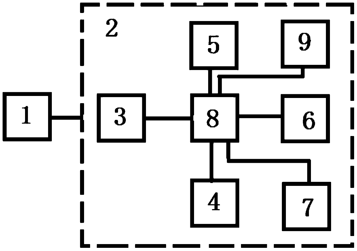
[0086] The fire source locating system is composed of three parts: an autonomous mobile robot 2, a host computer 1 platform and its communication peripherals. During specific implementation, in order to adapt to different ground environments, the autonomous mobile robot 2 may be a crawler robot (also called a crawler vehicle). A plurality of shock wheel sets are installed on the left and right sides of the robot body, and the shock wheel sets are used to ensure the safety of the connection of the components on the robot body. The tracked vehicle includes a temperature sensor 6, a smoke sensor 7, and a processor 8, which can independently complete fire extinguishing tasks, collect fire source information for processing and then send it to the host computer 1, and receive control instructions from the latter. The upper computer 1 platform and its communication peripherals realize the communication with the crawler robot, complete the remote PC control robot and process the data ...


PUM


Abstract

The invention discloses a fire source positioning method and system based on a SLAM technology and image identification. The method comprises the following steps of S1, constructing a real-time map and storing the map by an autonomous mobile robot through data returned by a laser radar and through combining with an SLAM algorithm; and S2, based on the established real-time map, carrying out autonomous travelling, capturing images through a camera and carrying out fire source identification and positioning; when the fire source identification and positioning are performed, firstly, carrying outHSV conversion on the images, processing the images in RGB and HSV spaces, and setting a threshold value to analyze a color so as to obtain an exact area of a similar fire source object; secondly, through determining whether smoke is generated, and a fire source temperature is reached, distinguishing an object with a color characteristic similar to the fire source and identifying the fire source;and finally, marking a center of the fire source in the image, carrying out inverse perspective processing on the image, converting an image coordinate into a real world coordinate, and determining the position and the distance of the fire source. In the invention, fire source identification precision is improved and the position of the fire source is determined.

Description

technical field [0001] The invention relates to a fire source location method and system based on SLAM technology and image recognition, and belongs to the technical field of fire source recognition and location. Background technique [0002] Most of the existing fire source identification and positioning systems use sensors such as smoke and temperature sensors for detection. They are generally only suitable for fire source positioning in small spaces, but in large spaces. There are many deficiencies. [0003] For the identification and positioning of fire sources in large spaces in fire-fighting scenarios, there is a method of simultaneous acquisition of video images and infrared images. Video images are manually monitored, and infrared images are used to find fire sources, but accurate identification and positioning of fire sources cannot be achieved. , and the later expansion is poor. The invention patent application with the application number 201710239808.9 discloses...

Claims


Application Information

Patent Timeline
IPC IPC(8): G01S17/89G01D21/02G05D1/12
CPCG01S17/89G01D21/02G05D1/12
Inventor 程龙黎家通孙浩李一帆万骏辉辛志强范晓静杨志雄余牧舟杨俊峰杨明杰高泽颖
Owner 东北大学秦皇岛分校
Why Eureka
Try Eureka