Fingerprint reading system

a fingerprint reading and fingerprint technology, applied in the field of fingerprint reading systems, can solve the problems of preventing readers from accurate authentication, affecting the accuracy of identification, so as to eliminate identification errors

Inactive Publication Date: 2016-08-30
LUSTROUS ELECTRO OPTIC
View PDF2 Cites 0 Cited by
  • Summary
  • Abstract
  • Description
  • Claims
  • Application Information

AI Technical Summary

Benefits of technology

[0011]The instant disclosure provides the following improvements. With the assembled camera module, control module, and signal processing module, the fingerprint reading system and method include automatic activation mechanisms and can eliminate identification errors from moving fingers.

Problems solved by technology

However, the bulk volume and cost of the prism in the contact optical fingerprint reader are quite high, and the surface of the prism requires surface treatment to prevent scratches and corrosive damages while fingers can easily leave dirt on the surface of the prism that requires cleaning, all of which prevent the readers from accurate authentication.
Moreover, the contact type readers cannot identify real fingerprints from synthetic fingerprint.
Alternatively, an expensive and high-end macro lens is required to provide deep depth of field effects in close proximity.

Method used


Image

  • Fingerprint reading system
  • Fingerprint reading system
  • Fingerprint reading system

Examples


first embodiment

[0018][First Embodiment]

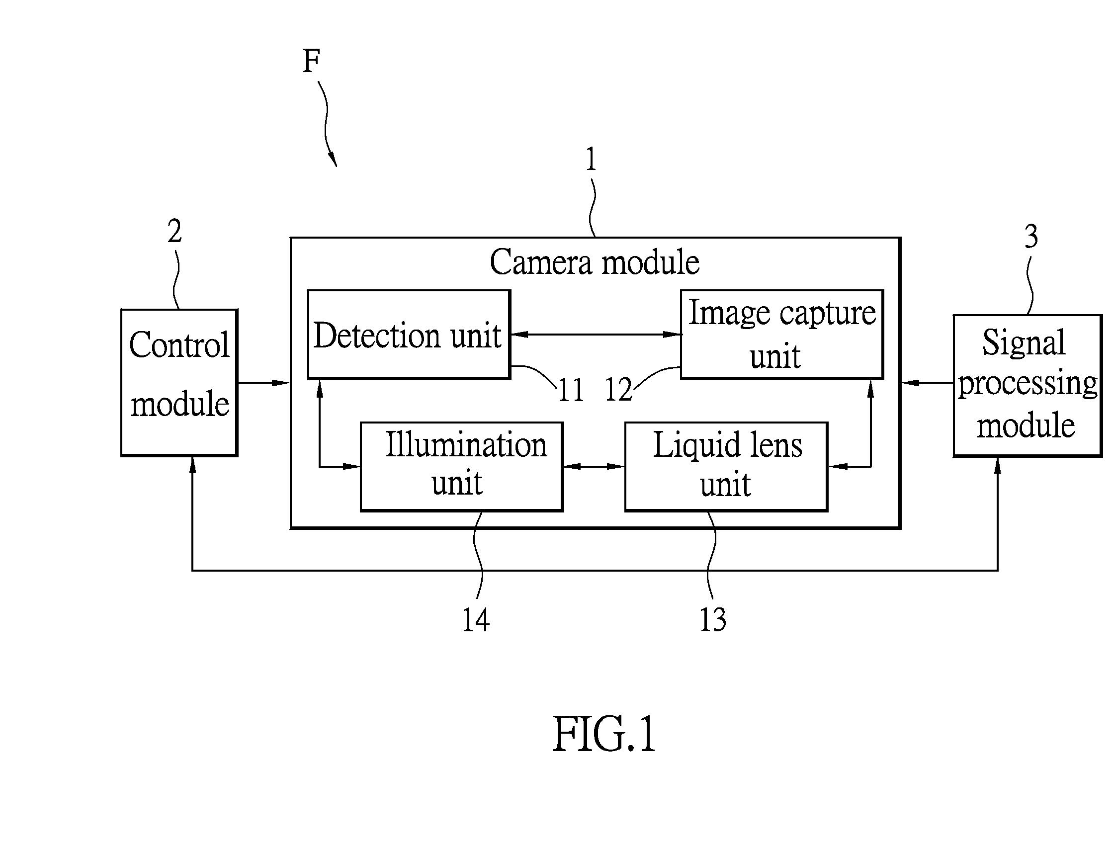
[0019]Please refer to FIG. 1. The first embodiment provides a fingerprint reading system F that includes a camera module 1, a control module 2, and a signal processing module 3. The camera module 1, control module 2, and signal processing module 3 are electrically connected to one another.

[0020]As shown in FIG. 1, the camera module 1 has a detection unit 11, an image capture unit 12, a liquid lens unit 13, and an illumination unit 14. The control module 2 controls the image capture unit 12, liquid lens unit 13, and the illumination unit 14. When the detection unit 11 detects a start signal, the control module 2 initiates or activates the image capture unit 12, the liquid lens unit 13, and the illumination unit 14. The start signal can be defined as the shape of the finger, color of the finger, or even a pre-determined area that is occupied by the finger that is accurately detected by the detection unit 11. For example, a finger occupies a half or one-third of...

second embodiment

[0026][Second Embodiment]

[0027]Please refer to FIG. 3. The second embodiment of the instant disclosure provides a method F200 for reading fingerprints that includes the following steps. An object is detected to determine whether the object is placed within the scanning region in step S200. The object can be detected by an active detection unit such as an infrared scanner, ultrasonic detector or even radar. Then as shown in step S202, properties of the object are determined in order to confirm whether or not the object is a finger. Properties can be the shape of the finger, the color of the finger, or the pre-determined area that the finger occupies in order to confirm authenticity of the fingerprint. For example, a third or one half of an image captured by the image capture unit 12 can first be analyzed and then the color or the shape of the finger is analyzed to confirm authenticity.

[0028]As shown in step S204, the illumination unit 14 is initiated or activated once the object is d...

third embodiment

[0031][Third Embodiment]

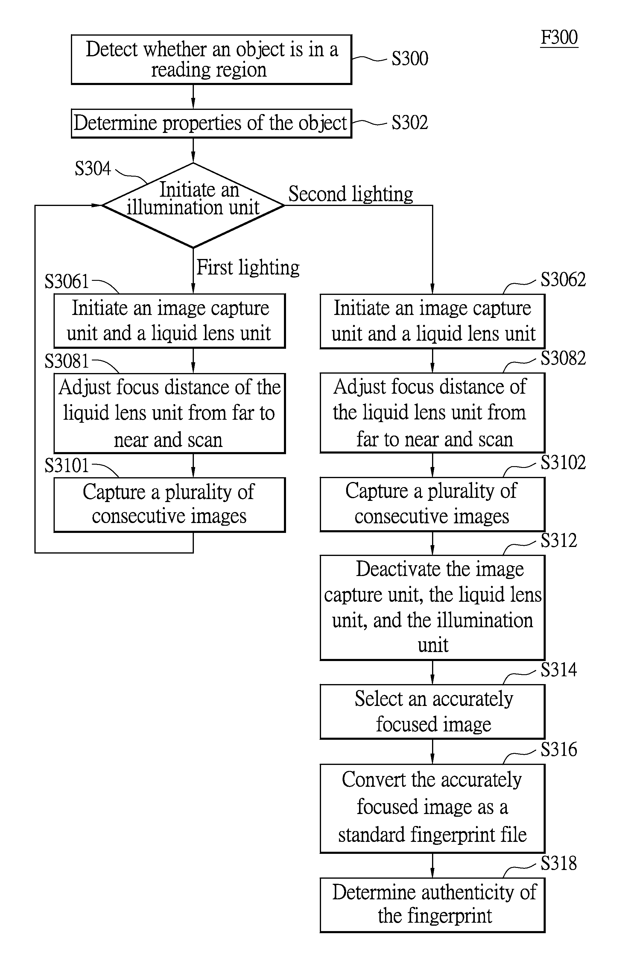
[0032]As shown in FIG. 4, a fingerprint reading method F300 is provided in a third embodiment of the instant disclosure. The third embodiment mainly differs from the second in that the illumination unit 14 irradiates different light rays onto the finger, in which different light rays have different effects on the finger, and the signal processing module 3 determines the authenticity of the fingerprint.

[0033]As shown in step S300, an object is detected to determine whether the object is placed within the scanning region. The object can be detected by an active detection unit such as an infrared scanner, ultrasonic detector or even radar. Then as shown in step S302, properties of the object are determined in order to confirm whether or not the object is a finger. Properties can be the shape of the finger, the color of the finger, or the pre-determined area that the finger occupies in order to confirm authenticity of the fingerprint. For example, a third or one ...


PUM


Abstract

A fingerprint reading system includes a camera module, a control module, and a signal processing module. The camera module has a detection unit, an image capture unit, a liquid lens unit, and an illumination unit. Control module is electrically connected to camera module for controlling the internal components of camera module. When the detection unit detects a start signal, the control module activates the image capture unit, liquid lens unit, and illumination unit. The liquid lens unit adjusts the focus distance across an entire scanning region and scans fingerprint. The image capture unit adjusts the focus distance across the entire scanning region through the liquid lens unit and scans fingerprint to capture multiple photos. The signal processing module selects the sharpest photo from the multiple photos to convert to a fingerprint image.

Description

BACKGROUND OF THE INVENTION[0001]1. Field of the Invention[0002]The instant disclosure relates to a fingerprint reading system; in particular, to a non-contact fingerprint reading system.[0003]2. Description of Related Art[0004]Personal electronic devices such as laptops or mobile phones typically retain user's personal information. To prevent others from obtaining personal information, access password is usually pre-set by the user to gain access to the personal electronic devices. However, access password can still be bypassed easily by other manners, thus allowing others to obtain personal information.[0005]Contact optical fingerprint readers are available that provide bright and dark fingerprint images because of full reflection of light onto the surface of a prism is intercepted by the ridge on a finger. However, the bulk volume and cost of the prism in the contact optical fingerprint reader are quite high, and the surface of the prism requires surface treatment to prevent scra...

Claims


Application Information

Patent Timeline
Patent Type & Authority Patents(United States)
IPC IPC(8): G06K9/62G06K9/00
CPCG06K9/00033G06V40/1312
Inventor TSAI, CHIH-WEI
Owner LUSTROUS ELECTRO OPTIC
Why Eureka
Try Eureka