Supercharge Your Innovation With Domain-Expert AI Agents!

Cliff detector, mobile robot and detection control method

A detection device and cliff technology, applied in the direction of program control manipulators, manipulators, manufacturing tools, etc., can solve problems such as machine misjudgment, machine failure, and machine failure

Active Publication Date: 2019-08-06
AMICRO SEMICON CORP
View PDF11 Cites 3 Cited by
  • Summary
  • Abstract
  • Description
  • Claims
  • Application Information

AI Technical Summary

Problems solved by technology

[0004] However, when the machine moves under strong sunlight, Yuba lighting (including strong infrared light interference), etc., the infrared receiving tube will easily enter the saturation state directly under the influence of strong light, resulting in the infrared receiving tube receiving no change. The amplitude signal is transmitted to the main control chip, which is easy to cause misjudgment; on the contrary, when the machine is in a normal lighting environment, when moving in a scene such as a black floor or a black carpet, the black ground medium absorbs infrared light, so that the infrared receiving tube receives a small amount of infrared light. The infrared receiving signal changes very little, and it is also easy to cause misjudgment by infrared detection, resulting in the machine not being able to walk normally or the risk of falling
Usually, in order to better adapt to the environment of the black ground, the working characteristics of the infrared emitting tube are adjusted, so that the sensing ability of the infrared receiving tube to infrared light is in a relatively sensitive state, but when the machine encounters problems such as In environments with strong infrared light interference such as strong sunlight and Yuba lights, the machine ground inspection may fail to work normally, or the machine may misjudge

Method used


Image

  • Cliff detector, mobile robot and detection control method
  • Cliff detector, mobile robot and detection control method
  • Cliff detector, mobile robot and detection control method

Examples


Embodiment Construction

[0018] The technical solutions in the embodiments of the present invention will be described in detail below with reference to the drawings in the embodiments of the present invention.

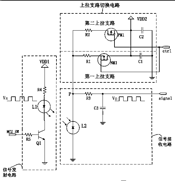
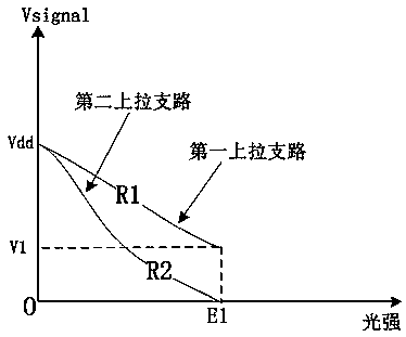
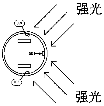
[0019] It should be noted that the anti-drop function of the intelligent sweeping robot is mainly realized by the ground detection sensor under the chassis of the machine, which is usually realized by the infrared emitting and receiving tubes. However, due to the differences in physical factors such as various ground environments, materials, and colors, Therefore, the reflection effect of the infrared light pulse signal on the corresponding ground medium is very different. For example, in the case of the same material and the same height from the ground, the reflection effect of the white ground is the best, and the reflection effect of the black ground is the worst.

[0020] An embodiment of the present invention provides a cliff detection device, and the cliff detection device is arranged on ...


PUM


Abstract

The invention discloses a cliff detector, a mobile robot and a detection control method. A signal emission circuit, a signal reception circuit and an upward pull branch switching circuit are included.The signal emission circuit is provided with an infrared emission control terminal. The signal reception circuit is provided with a cliff signal detection output end. The upward pull branch switchingcircuit is provided with an upward pull branch switching control terminal. The signal reception circuit and the upward pull branch switching circuit are provided with a common voltage induction node,wherein the voltage induction node is different from the upward pull branch switching control terminal and the cliff signal detection output end. The upward pull branch switching circuit comprises afirst upward pull branch and a second upward pull branch. The first upward pull branch and the second upward pull branch are each provided with a voltage node connected to the voltage induction node.The first upward pull branch and the second upward pull branch are each provided with the other voltage node connected to the upward pull branch switching control terminal. Therefore the earth detection signal detection limit is broadened, applicability of application environment is enhanced, and misjudgment conditions are reduced.

Description

technical field [0001] The invention belongs to the technical field of anti-drop detection, and in particular relates to a cliff detection device based on anti-glare misjudgment, a mobile robot and a detection control method. Background technique [0002] At present, due to its convenience, the sweeping robot has become a household item that more and more people will choose to use. Since the surface to be cleaned is often not completely on a plane, there are usually some structures such as steps. In the prior art, the ground inspection function of the sweeper is mainly realized by using infrared emitting and receiving tubes. Generally, an infrared sensor is installed on the chassis of the sweeper to detect in real time whether the machine has reached the edge of the ground. This capability can be called the cliff detection function. [0003] The infrared induction sensor includes an infrared emitting tube and an infrared receiving tube. The infrared emitting tube continuou...

Claims


Application Information

Patent Timeline
IPC IPC(8): B25J19/02B25J9/16
CPCB25J9/16B25J9/1676B25J19/02B25J19/021
Inventor 黄雄茂林立
Owner AMICRO SEMICON CORP
Features
  • R&D
  • Intellectual Property
  • Life Sciences
  • Materials
  • Tech Scout
  • Unparalleled Data Quality
  • Higher Quality Content
  • 60% Fewer Hallucinations
Learn More