
Roundness measuring frame and roundness measurement system having the same

A circular measuring frame and circular technology, applied in the field of circularity measurement, can solve the problems of large volume of circular parts, inconvenient measurement personnel, and high cost, and achieve the effects of accurate circularity calculation value, accurate measurement result, and fewer measurement points.

Pending Publication Date: 2019-08-06
CHINA INST OF WATER RESOURCES & HYDROPOWER RES
View PDF0 Cites 7 Cited by
  • Summary
  • Abstract
  • Description
  • Claims
  • Application Information

AI Technical Summary

Problems solved by technology

However, due to the large size and variety of circular parts, and the installation positions and heights are different, the roundness measurement requirements (including measurement accuracy requirements and measurement method requirements) are different, and different roundness measurements need to be designed for different circular parts. Device and circle measuring method, the cost is higher and brings great inconvenience to the measuring personnel

Method used


Image

  • Roundness measuring frame and roundness measurement system having the same
  • Roundness measuring frame and roundness measurement system having the same
  • Roundness measuring frame and roundness measurement system having the same

Examples


Embodiment Construction

[0037] An embodiment of the present invention provides a roundness measuring system for measuring the roundness of circular components, and is especially suitable for measuring the roundness of various circular rotating shafts in hydropower equipment.

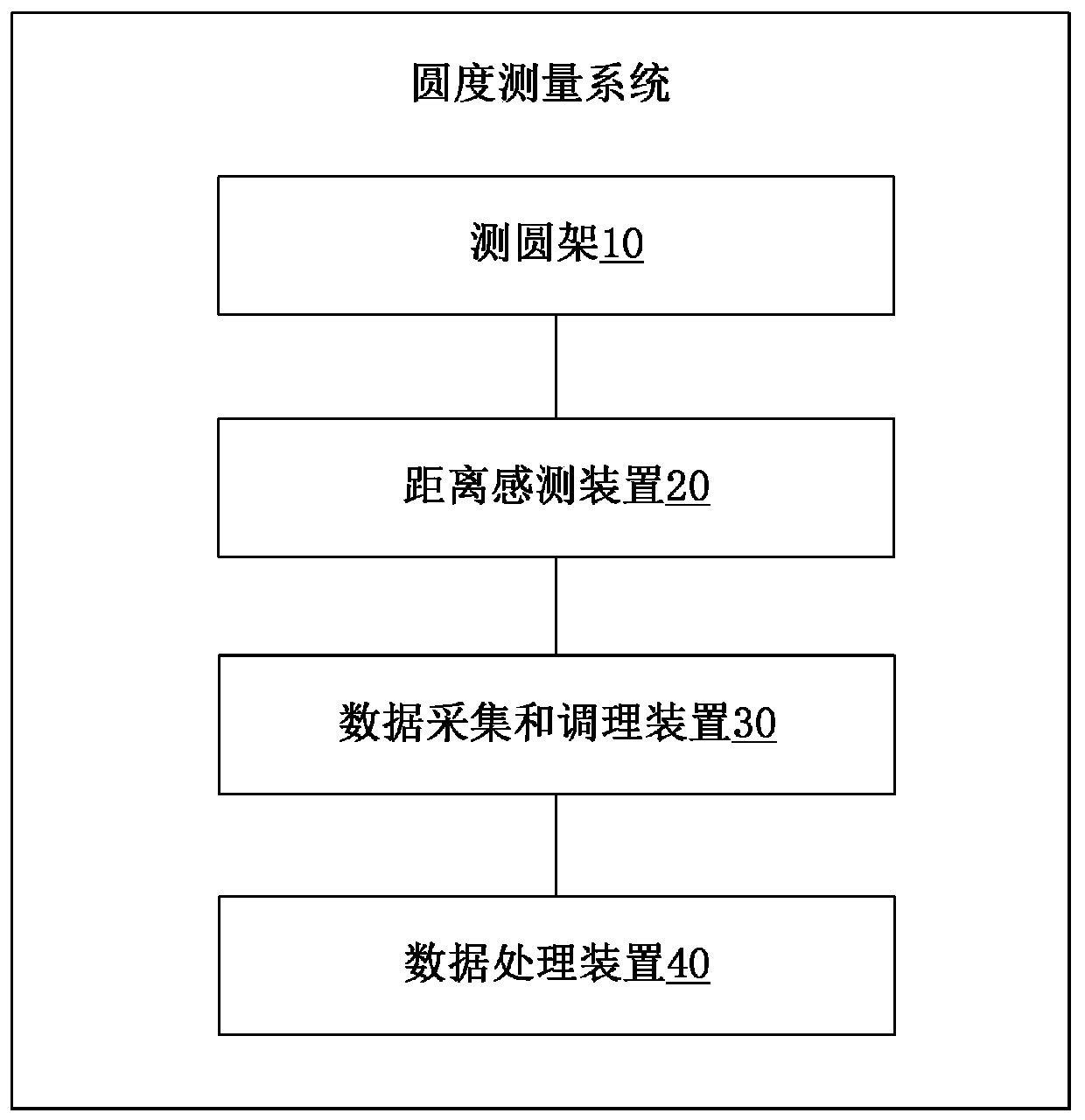
[0038] figure 1 is a schematic block diagram of a roundness measuring system according to an embodiment of the present invention. Such as figure 1 As shown, the roundness measurement system may generally include a circular measuring frame 10 , a distance sensing device 20 , a data acquisition and conditioning device 30 and a data processing device 40 .

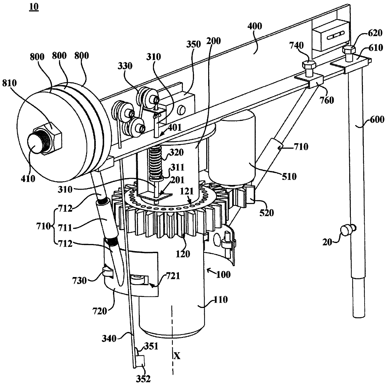
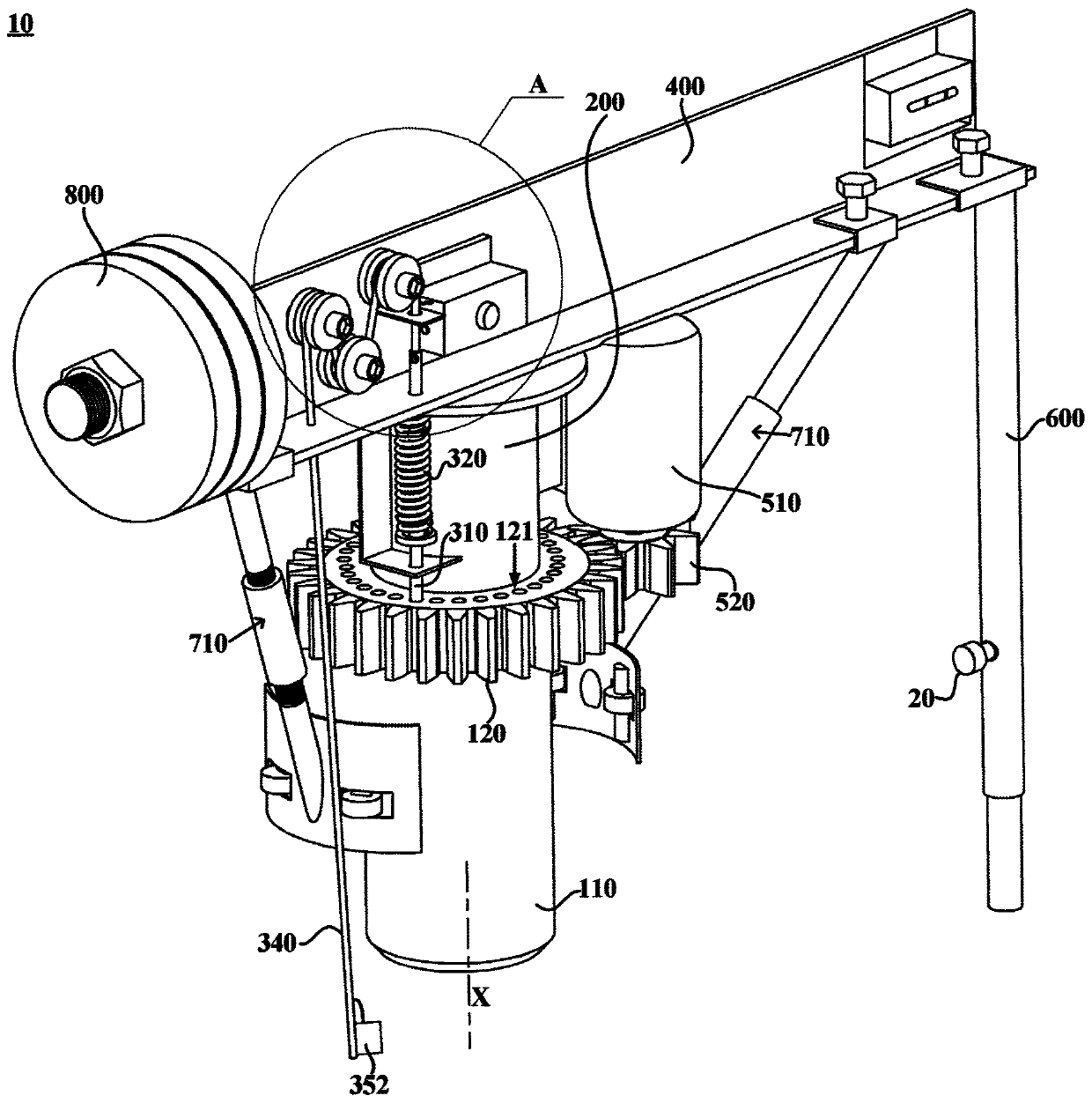
[0039] Wherein, the circular measuring frame 10 is used for installing the distance sensing device 20 , and can drive the distance sensing device 20 to rotate around the measured circular part through manual operation or driven by the motor 510 .

[0040] There is a gap between the distance sensing device 20 and the circumferential surface of the measured circular part. The ...


PUM


Abstract

The invention provides a roundness measuring frame and a roundness measurement system having the same. The roundness measuring frame comprises a positioning base, a rotating shaft, a motor, a connection arm, a measuring arm. A central axis is vertically extended and a plurality of positioning holes which are rotated symmetrically relative to the central axis are possessed. The rotating shaft is rotatably installed around the central axis and a positioning pin is possessed. The motor is used for driving the rotating shaft to rotate. The connection arm is fixed to the rotating shaft. A top end of the measuring arm is detachably fixed to the connection arm so as to install a distance sensing device. The roundness measuring frame is configured to make the rotating shaft be manually rotated, and make the positioning pin be inserted into a positioning hole to prohibit the rotation of the rotating shaft when the rotating shaft is rotated to make the positioning pin be opposite to a preset positioning hole so that the distance sensing device detects a radial spacing with a surface of a detected circular component; or the roundness measuring frame is configured to make the positioning pin be separated from the positioning hole, make the motor drive the measuring arm to rotate continuously and make the distance sensing device continuously detect the radial spacing with the surface of thedetected circular component. Suitable ranges of the roundness measuring frame and the roundness measurement system having the roundness measuring frame are wide.

Description

technical field [0001] The invention relates to the technical field of roundness measurement, in particular to a roundness measurement frame and a roundness measurement system with the same. Background technique [0002] Hydropower equipment includes many circular parts, such as the seat ring of the turbine, the leak-proof ring of the top cover and the bottom ring, the generator stator, the upper and lower frame of the generator, the upper and lower leak-proof rings of the generator stator, rotor, and the runner of the mixed flow turbine , The journal of each guide bearing of the unit, the large shaft flange and so on. [0003] The roundness needs to be measured during the processing and installation of these circular parts. However, due to the large size and variety of circular parts, and the installation positions and heights are different, the roundness measurement requirements (including measurement accuracy requirements and measurement method requirements) are differen...

Claims


Application Information

Patent Timeline
IPC IPC(8): G01B21/20G01B7/28
CPCG01B21/20G01B7/282G01B5/0002
Inventor 周叶潘罗平曹登峰刘永强谭志锋王俊杰郑云峰江翠伟邹志超
Owner CHINA INST OF WATER RESOURCES & HYDROPOWER RES
Learn More