X-ray grating imaging system and imaging method

A grating imaging and X-ray technology, applied in the field of X-ray imaging, can solve the problems of difficult to achieve comprehensive performance of X-ray imaging system, low efficiency of data acquisition process, high mechanical control requirements, etc. The effect of short time and improved scanning efficiency

Active Publication Date: 2021-03-05
TSINGHUA UNIV
View PDF1 Cites 0 Cited by
  • Summary
  • Abstract
  • Description
  • Claims
  • Application Information

AI Technical Summary

Problems solved by technology

Data collection process is inefficient and cumbersome
Some use the change of light source and grating to replace the stepping process, which brings new technical problems while solving the stepping problem, such as: blurring the image or reducing the image resolution in the Z direction due to the widening of the light source and position offset It is difficult to improve the overall performance of the X-ray imaging system due to problems such as high efficiency, high requirements for mechanical control, and long scanning time.

Method used


Image

  • X-ray grating imaging system and imaging method
  • X-ray grating imaging system and imaging method
  • X-ray grating imaging system and imaging method

Examples


no. 1 example

[0057] In a first exemplary embodiment of the present disclosure, an X-ray grating imaging system is provided.

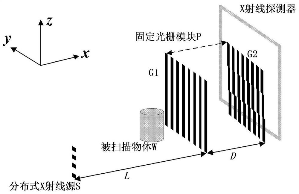
[0058] figure 1 It is a schematic structural diagram of an X-ray grating imaging system according to the first embodiment of the present disclosure.

[0059] refer to figure 1 As shown, the X-ray grating imaging system of the present disclosure includes: a distributed X-ray source S, which is perpendicular to the propagation direction of X-rays and distributed along a direction parallel to the grating stripes; a fixed grating module P, which is distributed along the direction of X-rays The propagation direction setting includes a first grating G1 and a second grating G2, the first grating G1 and the second grating G2 are parallel to each other and their relative positions are fixed; and an X-ray detector.

[0060] In the X-ray grating imaging system proposed in the present disclosure, the distributed X-ray source can switch exposure quickly. In this embodiment, t...

no. 2 example

[0089] In a second exemplary embodiment of the present disclosure, an X-ray grating imaging system is provided. In this embodiment, the grating type in the solution of the first embodiment and the specific setting of the position of the scanned object are exemplified. The X-ray grating imaging system of this embodiment is based on geometric projection grating imaging (incoherent grating phase lining imaging).

[0090] Figure 6A-6D It is a schematic diagram of some implementations of an X-ray grating imaging system based on geometric projection imaging (incoherent grating phase-contrast imaging) according to the second embodiment of the present disclosure.

[0091] In this embodiment, the distributed X-ray source is an incoherent ray source, and both the first grating G1 and the second grating G2 are absorption gratings. The specific setting positions of scanned objects and special types of gratings (including interlaced gratings and inclined gratings) can be changed: such a...

no. 3 example

[0094] In a third exemplary embodiment of the present disclosure, an X-ray grating imaging system is provided. In this embodiment, the grating type in the solution of the first embodiment and the specific setting of the position of the scanned object are exemplified. The X-ray grating imaging system of this embodiment is based on Talbot type grating imaging (coherent grating phase contrast imaging).

[0095] Figure 7A-Figure 7D It is a schematic diagram of some implementations of an X-ray grating imaging system based on Talbot-type imaging (coherent grating phase-contrast imaging) shown in the third embodiment of the present disclosure.

[0096] In this embodiment, the distributed X-ray source is an incoherent ray source, the first grating G1 is a phase grating and the second grating G2 is an absorption grating. The specific setting positions of scanned objects and special types of gratings (including interlaced gratings and inclined gratings) can be changed: such as Figu...


PUM


Abstract

An X-ray grating imaging system and imaging method, the system comprising: a distributed X-ray source, which is perpendicular to the propagation direction of the X-ray and distributed along a direction parallel to the grating stripes; a fixed grating module, which is distributed along the propagation direction of the X-ray The direction setting includes a first grating and a second grating, the first grating and the second grating are parallel to each other and their relative positions are fixed; and an X-ray detector. A group of stepping exposure processes based on the distributed X-ray source can obtain the light intensity at each pixel when the scanned object is included or not, so that the attenuation, phase contrast and One or several types of dark field information can be used to reconstruct images, and the overall system has the advantages of high system stability, short scanning time, low radiation dose and clear imaging.

Description

technical field [0001] The disclosure belongs to the technical field of X-ray imaging, and relates to an X-ray grating imaging system and an imaging method. Background technique [0002] In the prior art, X-ray scanning and imaging of objects has been widely used, such as CT scanning equipment, security inspection, X-ray machine, application in material flaw detection, and the like. Traditional X-ray scanning imaging generally uses the X-ray attenuation characteristics of the measured material to inspect the internal structure of the object in a non-destructive manner. The more obvious the difference in the density of the constituent structures of the various parts inside the object, the more significant the effect of traditional X-ray imaging techniques. However, substances made of light elements are weak absorbers for X-rays, so their internal structures can hardly be seen with conventional X-ray imaging techniques. Even if other auxiliary means are used, such as applyin...

Claims


Application Information

Patent Timeline
Patent Type & Authority Patents(China)
IPC IPC(8): G01N23/041
CPCG01N2223/03G01N2223/1016G01N23/041
Inventor 张丽吴承鹏高河伟邢宇翔
Owner TSINGHUA UNIV
Why Eureka
Try Eureka