Spin wave phase shifter based on polarization current control

A polarization current and spin wave technology, which is applied to waveguide-type devices, circuits, electrical components, etc., can solve the problems of low phase-shift accuracy loss, difficult to accurately control the position, and difficult to use, and achieve phase-shift stability and Excellent accuracy, reduced work energy consumption, and the effect of being conducive to miniaturization

Active Publication Date: 2019-08-06
UNIV OF ELECTRONIC SCI & TECH OF CHINA
View PDF2 Cites 6 Cited by
  • Summary
  • Abstract
  • Description
  • Claims
  • Application Information

AI Technical Summary

Problems solved by technology

The phase shifter based on the micro-magnetic structure is difficult to precisely control the micro-magnetic structure, and lacks simple and efficient control methods. For example, the drive of the common magnetic domain wall structure has excessive energy consumption and the position is difficult to control accurately. question
Y.Au et al.'s article "Nanoscale spin wave valve and phase shifter" ("Nanoscale spin valve and spin wave phase shifter") proposes a resonator-type spin wave phase shifter scheme, which has The phase shifter has the characteristics of high precision and low loss, but the disadvantage is that it cannot be adjusted manually, which makes the phase shifter have a narrow application range and is difficult to be practical

Method used


Image

  • Spin wave phase shifter based on polarization current control
  • Spin wave phase shifter based on polarization current control
  • Spin wave phase shifter based on polarization current control

Examples


Embodiment 1

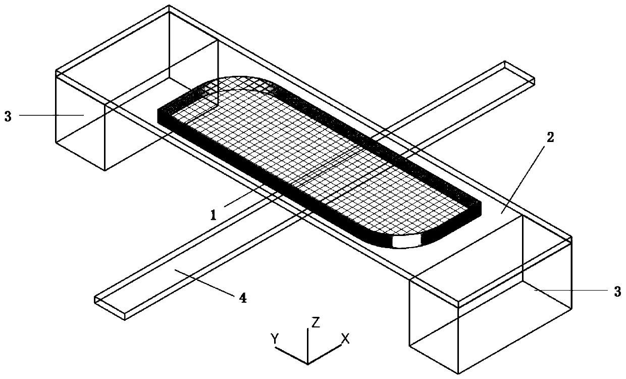
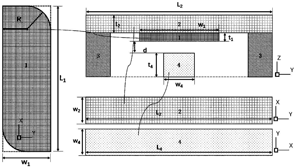
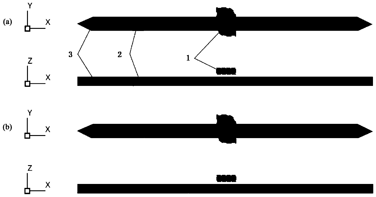
[0042] In the present embodiment, the size of the ferromagnetic layer as a resonator is: L 1 =150nm,w 1 =50nm, R=25nm, t 1 = 10nm; the size of the spin-wave waveguide is w 4 = 100nm, t 4 = 10nm, L 4 =2000nm; the size of the heavy metal layer is: L 2 =350nm, W 2 = 150nm, t 2 =30nm; the distance d between the spin-wave waveguide and the ferromagnetic layer=5nm; the spin-wave frequency is 10.5GHz. image 3 In the spin wave phase shifter provided by Embodiment 1 of the present invention, the schematic diagram when the magnetization state of the ferromagnetic layer is +y and -y; wherein, 1 and 3 are the spin wave waveguide and the ferromagnetic layer respectively, and 2 is Excited regions for spin waves. The phase shifter obtained in embodiment 1 is simulated, and the parameters are selected as follows: the ferromagnetic layer and the rectangular waveguide are permalloy, and its saturation magnetization Ms=8×10 5 A / m, anisotropy constant k=0J / m 3 , exchange constant A=12p...

Embodiment 2

[0044] In the present embodiment, the size of the ferromagnetic layer as a resonator is: L 1 =150nm,w 1 =50nm, R=25nm, t 1 = 2nm; the size of the spin wave guide is w 4 =50nm,t 4 = 4nm, L 4 =2000nm; the size of the heavy metal layer is: L 2 =350nm, W 2 = 150nm, t 2 =30nm; the distance d between the spin-wave waveguide and the ferromagnetic layer=2nm; the spin-wave frequency is 10.5GHz. The phase shifter obtained in embodiment 2 is simulated, and the parameters are selected as follows: the ferromagnetic layer and the rectangular waveguide are permalloy, and its saturation magnetization Ms=8×10 5 A / m, anisotropy constant k=0J / m 3 , exchange constant A=12pJ / m, damping coefficient α=0.005, polarization current density J=1e13J / m 2 . Figure 5 The simulation result of the spin wave phase shifter provided for the embodiment 2 of the present invention at a certain moment after the spin wave transmission is stable; wherein, (a) is the waveform diagram of the waveguide without...


PUM


Abstract

The invention relates to a spin wave phase shifter based on polarization current control, and belongs to the technical field of magnon devices. The spin wave phase shifter comprises a spin wave waveguide 4, a ferromagnetic layer located above the spin wave waveguide, a heavy metal layer 2 located on the ferromagnetic layer 1 and two electrodes 3 which are connected with two ends of the heavy metallayer and used for introducing current, wherein there is a spacing between the spin wave waveguide 4 and the ferromagnetic layer 1, the long side of the ferromagnetic layer is perpendicular to the transmission direction of the spin wave waveguide, the ferromagnetic layer is of an asymmetric structure so as to generate shape anisotropy. The spin wave phase shifter based on polarization current control realizes the control through an SOT effect, and the required current intensity is small. Compared with the overturn of the existing polarization current control ferromagnetic materials, the relaxation result of the ferromagnetic layer depends on the shape anisotropy thereof and can be implemented by only introducing current pulse for a short time, and the efficiency and energy consumption aremore advantageous.

Description

technical field [0001] The invention belongs to the technical field of magnon devices, and in particular relates to an attached spin wave phase shifter based on polarization current control. Background technique [0002] The development of traditional CMOS devices is facing the dual pressure of technology and cost. In the long run, because the development of traditional charge-type devices in high-frequency and low-scale environments is limited by inherent conditions, the development of new super-CMOS devices, namely "non-charge-type "Device" will be the only way for the development of integrated circuits in the future. Among many "beyond CMOS" devices, spintronic devices are one of the strong competitors. [0003] Spin is an intrinsic property of subatomic particles such as electrons, which belongs to the category of quantum mechanics. Since the spin interaction between electrons is much smaller than the interaction between electron charges, it is much simpler to change t...

Claims


Application Information

Patent Timeline
IPC IPC(8): H01P1/18H01P1/19
CPCH01P1/182H01P1/19
Inventor 钟智勇张子康刘爽文天龙廖宇龙金立川唐晓莉张怀武
Owner UNIV OF ELECTRONIC SCI & TECH OF CHINA
Why Eureka
Try Eureka