Adjustable magnetic valve

A solenoid valve, adjustable technology, applied in the field of solenoid valves, can solve problems such as costly adjustment process

Active Publication Date: 2018-12-04
ROBERT BOSCH GMBH
View PDF6 Cites 2 Cited by
  • Summary
  • Abstract
  • Description
  • Claims
  • Application Information

AI Technical Summary

Problems solved by technology

Furthermore, complex adjustment procedures are required for the air gap between pole piece and valve armature when assembling an adjustable normally closed solenoid valve

Method used


Image

  • Adjustable magnetic valve
  • Adjustable magnetic valve
  • Adjustable magnetic valve

Examples


Embodiment Construction

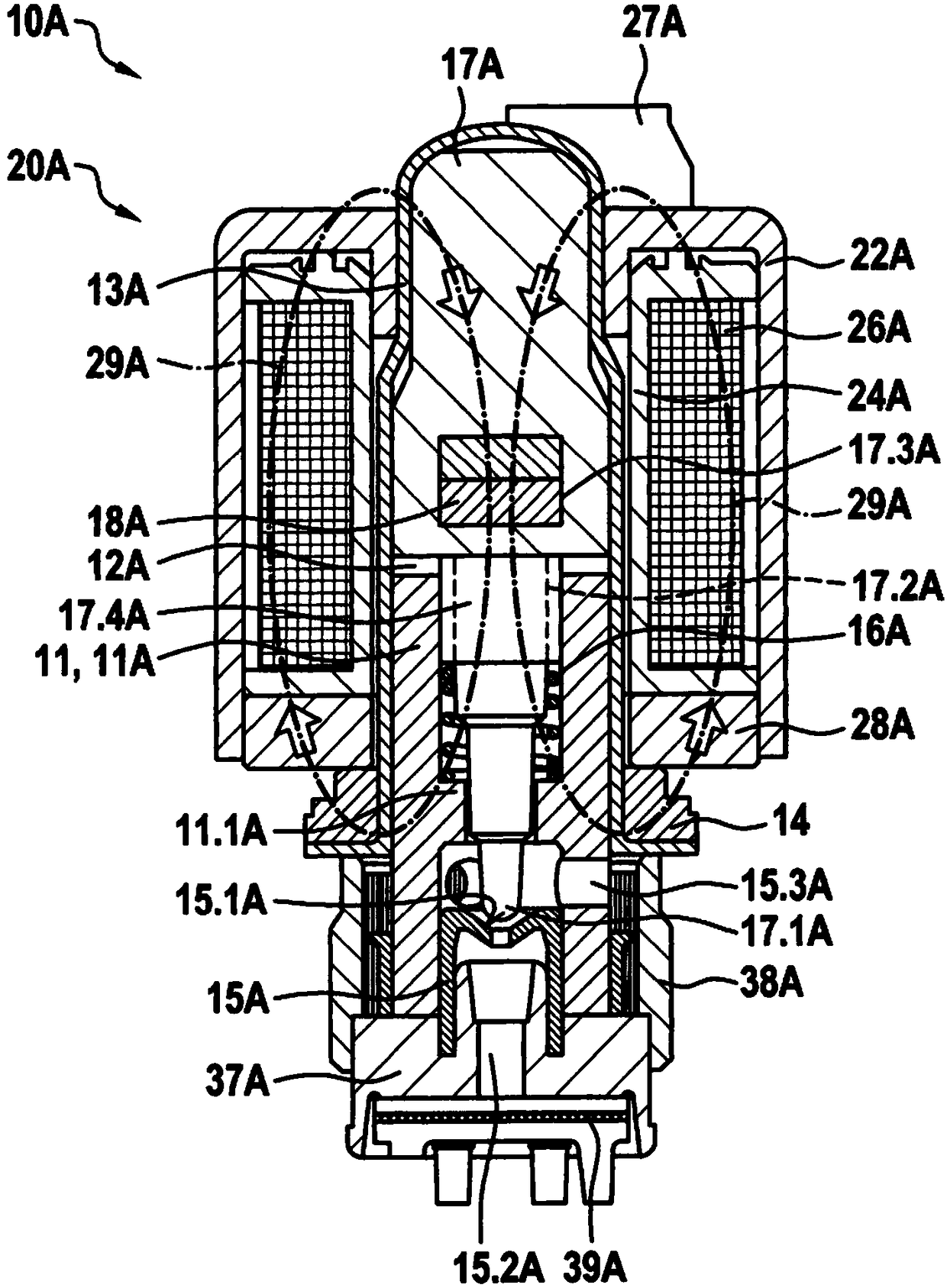
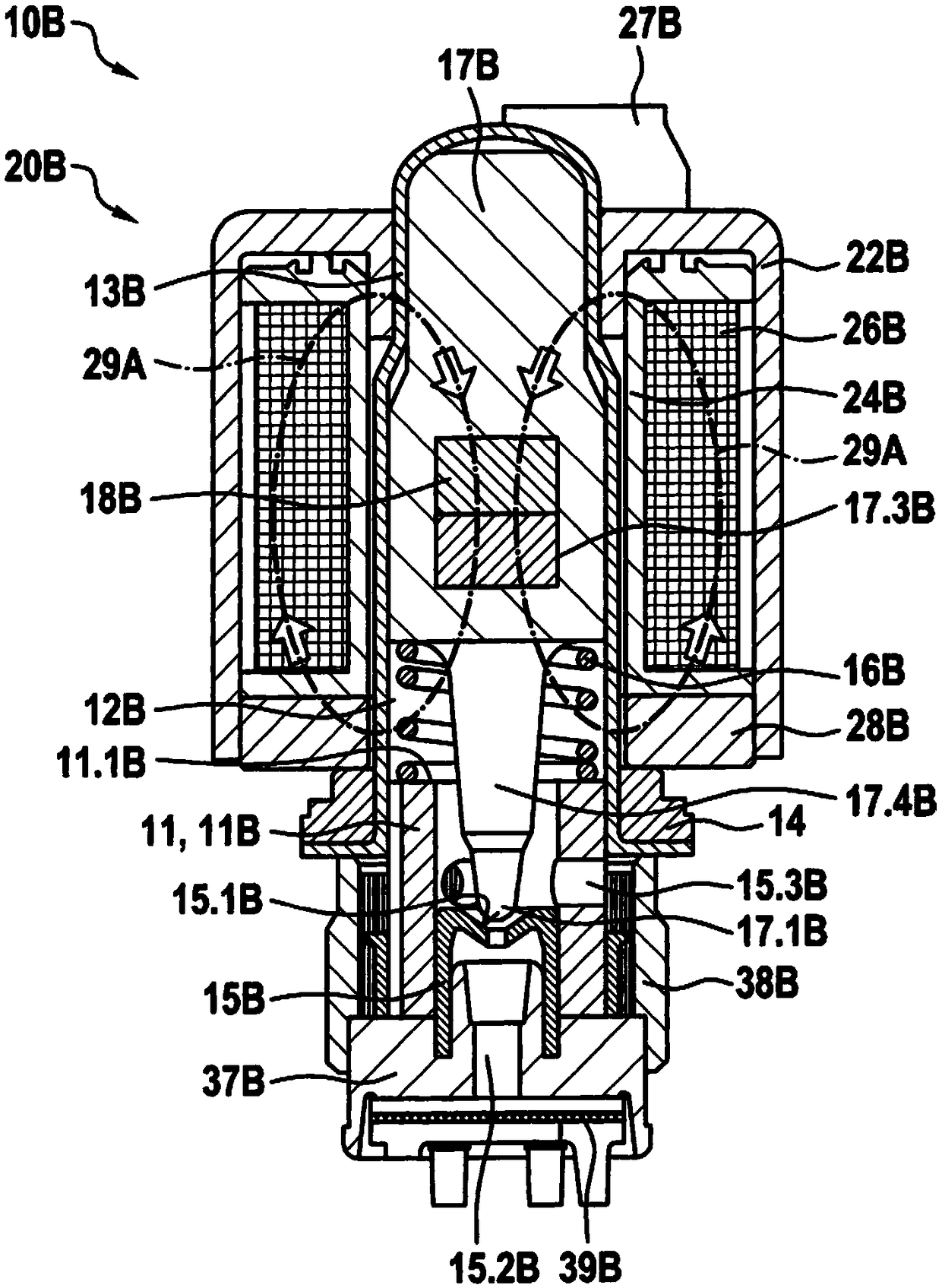
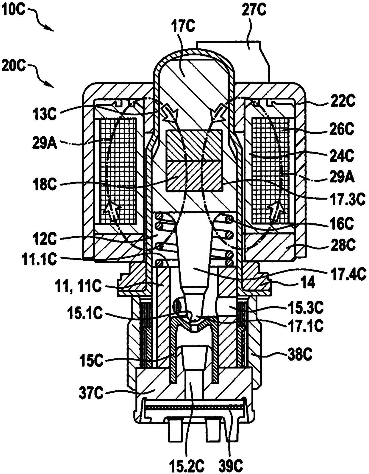
[0022] as by Figure 1 to Figure 5 As shown, the illustrated embodiments of adjustable solenoid valves 10A, 10B, 10C, 10D, 10E according to the present invention respectively include a magnet assembly 20A, 20B, 20C, 20D, 20E and a guide sleeve 13A, 13B, 13C, 13D, 13E, the immovable part 11 is fixedly arranged in said guide sleeve and the valve armature 17A, 17B, 17C, 17D, 17E can overcome the force of the return spring 16A, 16B, 16C, 16D, 16E The force is arranged axially displaceable in the guide sleeve. The magnet assembly 20A, 20B, 20C, 20D, 20E is pushed onto the immovable part 11 formed for the valve and the guide sleeve 13A, 13B, 13C, 13D, 13E. Axial stops of the armatures 17A, 17B, 17C, 17D, 17E. Said valve armatures 17A, 17B, 17C, 17D, 17E are actuatable by magnetic forces generated by energized magnet assemblies 20A, 20B, 20C, 20D, 20E, and during movement in the blocking direction move the blocking elements 17.1A, 17.1B . D, 17.1E are lifted from valve seats 15.1...


PUM


Abstract

The invention relates to an adjustable magnetic valve (10A) which includes a magnet assembly (20A) and a guide sleeve (13A) in which a static component (11) is arranged fixedly and a valve armature (17A) is arranged so as to be axially displaceable therein. The magnet assembly (20A) is pushed onto the static component (11) and the guide sleeve (13A). The static component (11) forms an axial stop for the valve armature (17A), which either forces a closing element (17.1A) into a valve seat (15.1A) or lifts the closing element from the valve seat (15.1A) depending on the direction in which the valve armature is driven. The valve armature (17A) and the static component (11) are each formed as plastic components. The valve armature (17A) has a magnet receptacle (17.3A) that receives a permanentmagnet (18A) which is polarized in terms of its movement direction such that the permanent magnet (18A) is arranged within the magnet assembly (20A) regardless of the armature stroke.

Description

technical field [0001] The invention relates to an adjustable solenoid valve of the type according to independent claim 1 . Background technique [0002] In hydraulic brake systems with the ESP function (ESP: Electronic Stability Program), adjustable solenoid valves are always used for the different functions, wherein the desired valve travel is firstly determined by the force balance between spring force and hydraulic pressure, On the other hand, adjustment takes place via the balance of forces between spring force and magnetic force. The difficulty of adjustment is increased by the strong non-linearity of the magnetic force as a function of the air gap in the magnetic circuit between the movable valve armature and the non-movable part. As the air gap decreases, the magnetic force increases excessively, so that for example disturbances such as pressure pulses in a hydraulic system can lead to greater changes in the magnetic force at smaller air gaps. In order to compensat...

Claims


Application Information

Patent Timeline
Patent Type & Authority Applications(China)
IPC IPC(8): F16K31/08B60T8/36
CPCB60T8/36F16K31/0655F16K31/0662F16K31/0665F16K31/0675F16K31/082B60T13/686B60T8/363B60T8/367B60T2270/30B60T15/36B60T8/17B60T8/00
Inventor E·库尔茨M·亚姆布罗西M·埃森劳尔W·斯塔尔W·舒勒
Owner ROBERT BOSCH GMBH
Why Eureka
Try Eureka