


Quick Research
Generate reliable direction feasibility study reports for your R&D in just a few steps.

Technical Q&A
Discover and master advanced knowledge NOW. Basics, ideas, possibilities, all at once.

Find Solutions
As an expert in R&D theories, this can generate solutions to your technical problems instantly.

Evaluate Feasibility
Analyze your overall solution with one click, know your potential R&D risks in advance.

Monitor Landscape
Get weekly tech updates, stay abreast of the latest tech innovations and key insights.
Coke oven regenerative chamber
A technology for regenerators and coke ovens, which is applied in the heating of coke ovens, coke ovens, coke oven parts, etc., and can solve the problems of low denitrification efficiency and poor use effect of ammonia-containing gas
- Summary
- Abstract
- Description
- Claims
- Application Information
AI Technical Summary
Problems solved by technology
Method used
Image

Examples
Embodiment 1
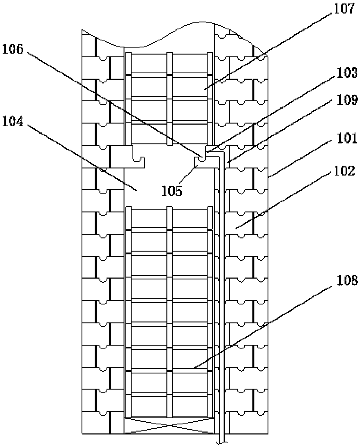
[0049] This embodiment provides a coke oven regenerator, including:
[0050] The coke oven regenerator body 101, including the first furnace wall 102;
[0051] The gas inlet 103 is arranged on the first furnace wall 102, and is used to receive the ammonia-containing gas so that the ammonia-containing gas flows into the denitration area 104 inside the coke oven regenerator body 101;
[0052] The gas distribution device includes a stopper 105, the stopper 105 is arranged inside the coke oven regenerator body 101, and is located below the gas inlet 103, and the top surface of the stopper 105 is used to contact the Ammonia-containing gas to change the flow direction of the ammonia-containing gas.
[0053] Thus, when the coke oven regenerator is in use, ammonia-containing gas enters the coke oven regenerator body 101 through the gas inlet 103, the temperature inside the coke oven regenerator is high, and the temperature of the ammonia-containing gas is low , so after the ammonia-...
Embodiment 2
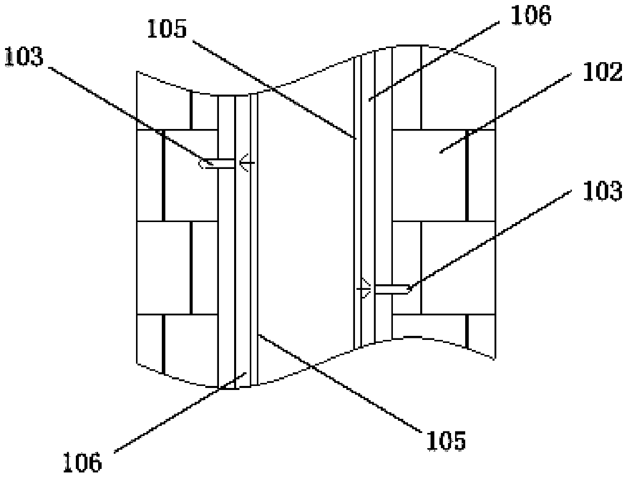
[0059] combined with figure 1 , attached figure 2, on the basis of Embodiment 1, there are multiple gas inlets 103, a plurality of gas inlets 103 are arranged at intervals along the length direction of the furnace wall, and the top surface of the stopper 105 is along the first furnace wall 102 extends lengthwise.
[0060] Therefore, preferably, one or more grooves 106 are provided on the top surface of the block 105, and the grooves 106 extend along the horizontal direction of the furnace wall. Setting the groove 106 can make the ammonia-containing gas continue to flow along the groove 106 after contacting the top surface of the stopper 105, instead of directly flowing downward, thereby further increasing the ammonia-containing gas and the The mixing time of the gas inside the regenerator in the denitration area 104.
[0061] As a preferred implementation of this embodiment, the coke oven regenerator further includes regenerator bricks, and the regenerator bricks include a...
Embodiment 3
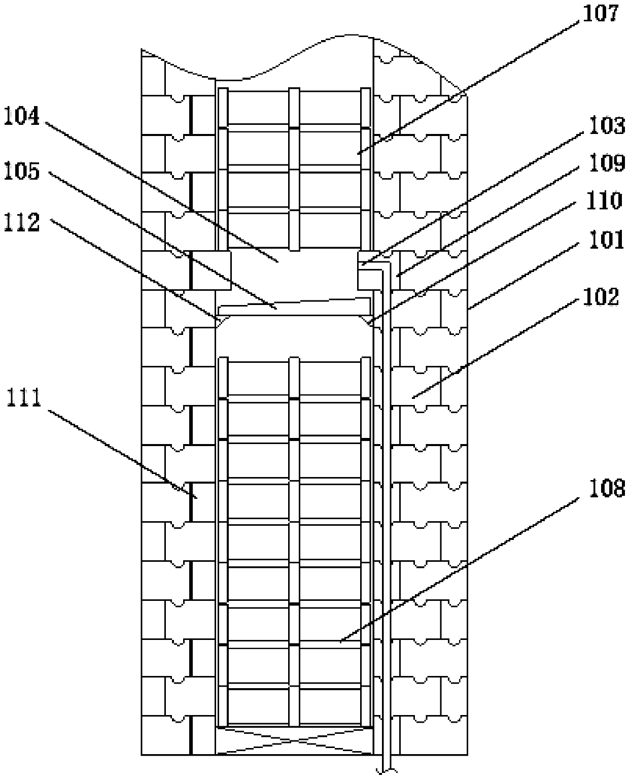
[0064] combined with image 3 , attached Figure 4 , as a preferred implementation of this embodiment, on the basis of Embodiment 1, the gas distribution device further includes a support, and the support is connected or overlapped with the block 105 and the coke oven regenerator body 101 , so that there is a set distance between the top surface of the stopper 105 and the bottom of the coke oven regenerator body 101 .
[0065] As a preferred implementation of this embodiment, the support includes a first support 110, the first support 110 is arranged on the first furnace wall 102, and is connected to one end of the block 105; As a preferred implementation of this embodiment, the coke oven regenerator further includes a second furnace wall 111, the second furnace wall 111 is opposite to the first furnace wall 102, and the support member further includes a second A support 112 , the second support 112 is arranged on the second furnace wall 111 and connected to the other end of...
PUM
| Property | Measurement | Unit |
|---|---|---|
| Width | aaaaa | aaaaa |
| Thickness | aaaaa | aaaaa |
Abstract
Description
Claims
Application Information
 - R&D Engineer
- R&D Manager
- IP Professional
- Industry Leading Data Capabilities
- Powerful AI technology
- Patent DNA Extraction
Browse by: Latest US Patents, China's latest patents, Technical Efficacy Thesaurus, Application Domain, Technology Topic, Popular Technical Reports.
© 2024 PatSnap. All rights reserved.Legal|Privacy policy|Modern Slavery Act Transparency Statement|Sitemap|About US| Contact US: help@patsnap.com