Tapered section vortex generator and mounting method thereof

A technology of vortex generators and vortex generation, which is applied to wind turbines, engines, wind power generation, etc. in the same direction as the wind, and can solve the problems of affecting the power enhancement effect of vortex generators, very limited wake disturbance, and poor flow separation effects, etc. , to achieve the effect of inhibiting the three-dimensional flow of the leaf root, good promotion value, and simple structure

Active Publication Date: 2019-08-09
SHANGHAI ELECTRIC WIND POWER GRP CO LTD
View PDF10 Cites 4 Cited by
  • Summary
  • Abstract
  • Description
  • Claims
  • Application Information

AI Technical Summary

Problems solved by technology

Since the fins of the vortex generator are arranged in a "eight" shape, the drag coefficient of the airfoil will increase, which will affect the overall power enhancement effect of the vortex generator
However, if there is no such included angle

Method used


Image

  • Tapered section vortex generator and mounting method thereof
  • Tapered section vortex generator and mounting method thereof
  • Tapered section vortex generator and mounting method thereof

Examples


Embodiment Construction

[0040] The following will clearly and completely describe the technical solutions in the embodiments of the present invention with reference to the accompanying drawings in the embodiments of the present invention. Obviously, the described embodiments are only some, not all, embodiments of the present invention. Based on the embodiments of the present invention, all other embodiments obtained by persons of ordinary skill in the art without making creative efforts belong to the protection scope of the present invention.

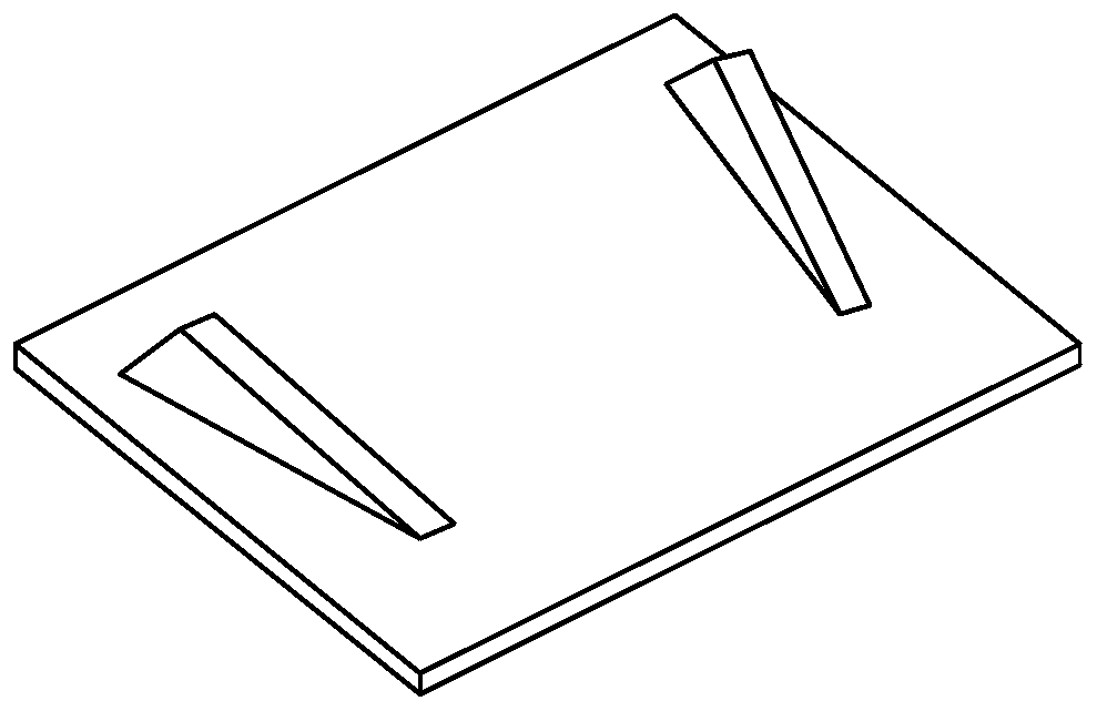
[0041] The structure of wind turbine blade 4 is as follows: Figure 15 shown. A wind turbine is usually installed as Figure 15 Three wind turbine blades 4 are shown. Such as Figure 15 As shown, the two ends of the wind turbine blade 4 are the blade root 1 and the blade tip 2 respectively, and the blade root is connected to the hub of the wind turbine blade. The direction perpendicular to the wind power blade is the normal direction, the direction from th...


PUM


Abstract

The invention provides a tapered section vortex generator. The tapered section vortex generator is provided with a hollow structure with the two open ends; the first end and the second end of the vortex generator are both open ends, the end faces of the two ends are flush, the first end of the vortex generator is a flowing inlet end, and the second end of the vortex generator is a flowing outlet end; the area of the section, perpendicular to a central line, of the vortex generator is tapered from the first end of the vortex generator to the second end of the vortex generator; the inner profileand the outer profile of the vortex generator are in smooth transition from the first end of the vortex generator to the second end of the vortex generator; and the central line of the vortex generator is parallel to the flowing direction, and the outer profile of the vortex generator is fixedly bonded on the profile of a wind power blade. The invention further provides a mounting method of the vortex generator. According to the vortex generator, lift force of the wind power blade can be increased, the electric quantity is increased, and the vortex generator is especially suitable for wind fields of low wind speed zones and low air density areas.

Description

technical field [0001] The invention relates to the field of wind power generation equipment, in particular to a vortex generator with a tapering section. Background technique [0002] Several vortex generators are usually installed on the blades of modern wind turbines to generate high-energy wingtip vortices, suppress flow separation on the upper surface of the airfoil, delay stall, and increase power generation. Such as figure 1 The common vortex generator structure shown includes two symmetrically distributed fins and a base. The fins are usually perpendicular to the base and form a certain angle with the flow direction. Regarding the shape of the fins, many patents have published different design schemes. The geometric shape of the vortex generator produces a wingtip "vortex" similar to the wingtip of an aircraft in the flow field. The wingtip "vortex" brings the energy of the high-speed fluid outside the boundary layer into the boundary layer through rotation, increa...

Claims


Application Information

Patent Timeline
IPC IPC(8): F03D80/00F03D1/06
CPCF03D1/0675F03D80/00F05B2240/3062Y02E10/72
Inventor 艾国远赵大文李海涛
Owner SHANGHAI ELECTRIC WIND POWER GRP CO LTD
Why Eureka
Try Eureka