Vortex generator, fan blade and manufacturing method thereof

A technology for vortex generators and fan blades, applied in the field of fan blades and their manufacture, and vortex generators, can solve the problems of increasing the production cost of blades, long production cycle of blades, difficult maintenance and cleaning, etc., so as to suppress the three-dimensional flow of blade roots and improve Annual power generation and the effect of reducing aerodynamic noise

Inactive Publication Date: 2019-08-02
SHANGHAI ELECTRIC WIND POWER GRP CO LTD
View PDF5 Cites 2 Cited by
  • Summary
  • Abstract
  • Description
  • Claims
  • Application Information

AI Technical Summary

Problems solved by technology

Under the requirements of the existing technology, it is necessary to attach more vortex generator units on the surface of the blade, and the number is large. Once the patch is completed, it needs to be reliable for several years. Therefore, there are also high technical requirements for the patch, and the guarantee is 20 It is very difficult not to damage or fall off
In addition, adding a large number of aerodynamic accessories on the surface of the blade also caused an increase in the quality of the blade, requiring additional thickening of the blade root and tower
These problems all increase the production cost of the blade and cause the blade production cycle to be long, and the later maintenance and cleaning are difficult, etc.

Method used


Image

  • Vortex generator, fan blade and manufacturing method thereof
  • Vortex generator, fan blade and manufacturing method thereof
  • Vortex generator, fan blade and manufacturing method thereof

Examples


Embodiment Construction

[0036] In order to make the purpose, technical solutions and advantages of the embodiments of the present invention clearer, the technical solutions in the embodiments of the present invention will be clearly and completely described below in conjunction with the drawings in the embodiments of the present invention. Obviously, the described embodiments It is a part of embodiments of the present invention, but not all embodiments. Based on the embodiments of the present invention, all other embodiments obtained by persons of ordinary skill in the art without making creative efforts belong to the protection scope of the present invention.

[0037] The following combination Figure 3 ~ Figure 7 , the technical solution of the present invention will be described in detail with specific examples. The following specific embodiments may be combined with each other, and the same or similar concepts or processes may not be repeated in some embodiments.

[0038] image 3 A schematic ...


PUM

PropertyMeasurementUnit
lengthaaaaaaaaaa
depthaaaaaaaaaa
widthaaaaaaaaaa

Abstract

The invention discloses a vortex generator, a fan blade and a manufacturing method thereof. The vortex generator comprises a groove formed in a blade, wherein the groove gradually reduces; and when gas flow flows through near the groove, high-energy vortex is generated under action of the groove, and develops towards the downstream to disturb gas flow on the upper surface of the blade. According to the vortex generator disclosed by the invention, blade quality is reduced, the producing and mounting period of the vortex generator is reduced in process, and certain cost reducing meaning is achieved; besides, the vortex generator is integrally formed along with the blade main body, and attachments do not need to paste to the surface of the blade, so that compared with a conventional mountingtype vortex generator, the vortex generator disclosed by the invention has extremely high reliability, is convenient in later-stage operation and maintenance, can meet main functions of an existing vortex generator, can generate enough disturbance vortex to inhibit downstream flow separation, and delays speed reduction.

Description

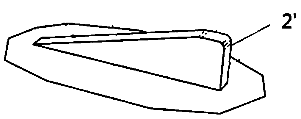
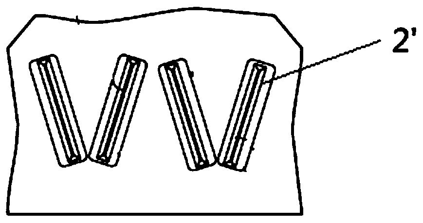
technical field [0001] The invention relates to the field of fan power generation blades, in particular to a vortex generator, a fan blade and a manufacturing method thereof. Background technique [0002] Several vortex generators are usually installed on the blades of modern wind turbines to generate high-energy wingtip vortices, suppress flow separation on the upper surface of the airfoil, delay stall, and increase power generation. A typical vortex generator structure is as figure 1 shown. It includes two symmetrically distributed fins and a base. The fins are usually perpendicular to the base and form a certain angle with the flow direction. Various patents have disclosed the shape of several fins 2', such as Figure 2a-2e shown. The geometric shape of the vortex generator produces a wingtip "vortex" similar to the wingtip of an aircraft in the flow field. The wingtip "vortex" brings the energy of the high-speed fluid outside the boundary layer into the boundary layer...

Claims


Application Information

Patent Timeline
Patent Type & Authority Applications(China)
IPC IPC(8): F03D1/06F03D15/00B29C70/36B29L31/08
CPCB29C70/36B29L2031/085F03D1/0675F03D15/00Y02E10/72Y02P70/50
Inventor 艾国远许移庆李海涛赵大文
Owner SHANGHAI ELECTRIC WIND POWER GRP CO LTD
Why Eureka
Try Eureka