Aerodynamic structure for aircraft wing
a technology for aerodynamic structures and aircraft wings, applied in heat reducing structures, air-flow influencers, transportation and packaging, etc., can solve the problems of airflow separation, degrading downstream boundary layers, and exposed inner faces of slat recesses, so as to improve aerodynamic and/or flight properties of wings, the effect of minimising drag
- Summary
- Abstract
- Description
- Claims
- Application Information
AI Technical Summary
Benefits of technology
Problems solved by technology
Method used
Image
Examples
first embodiment
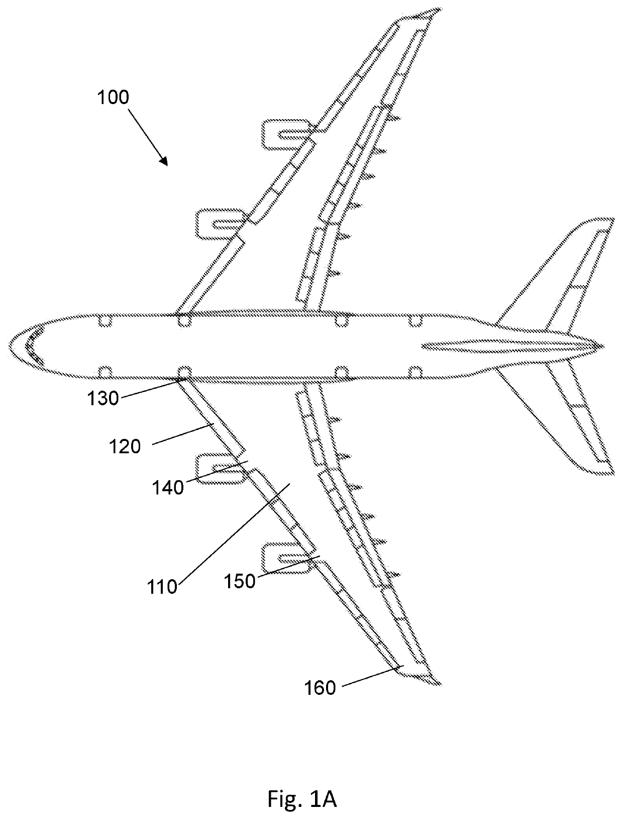
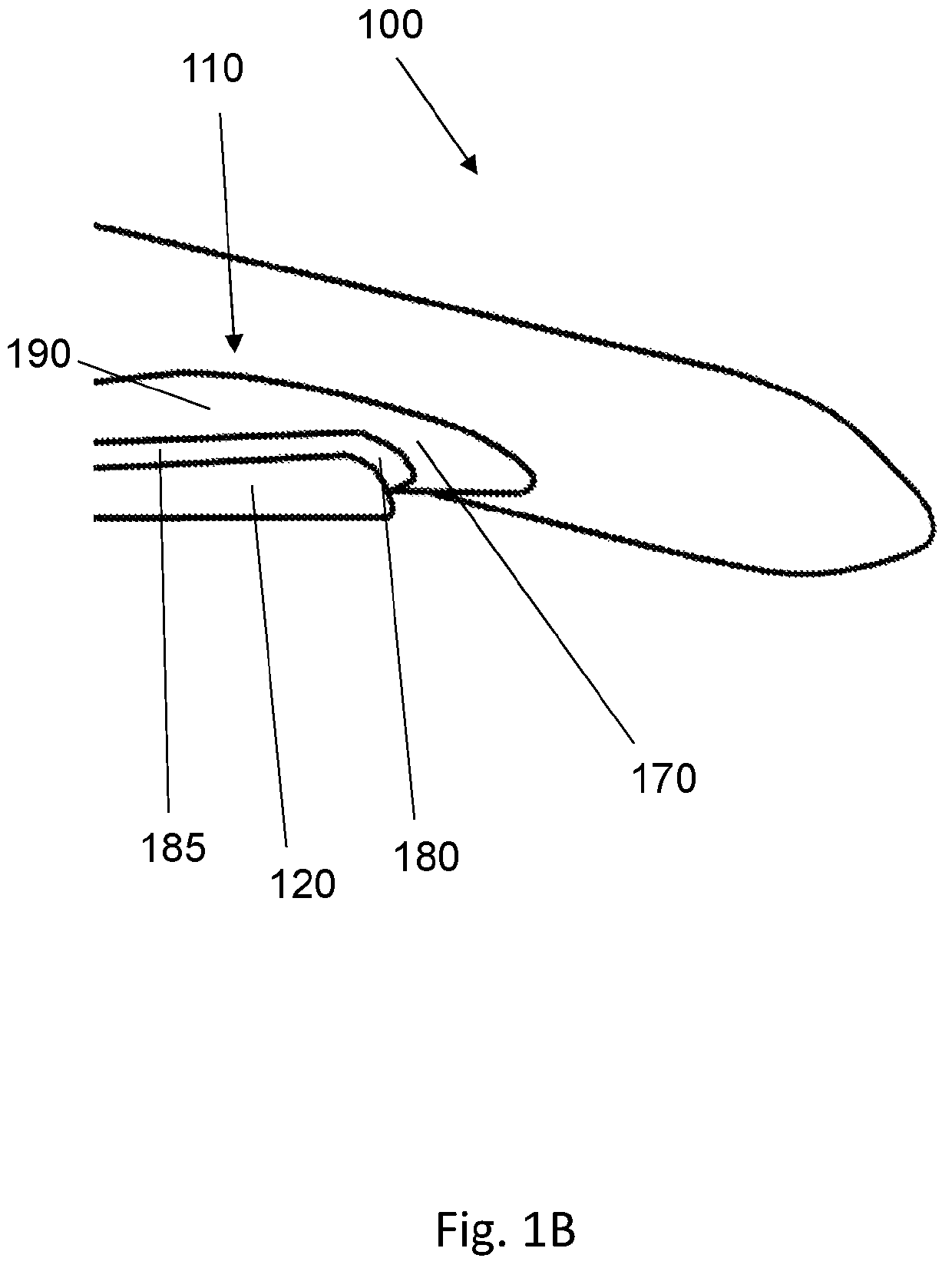
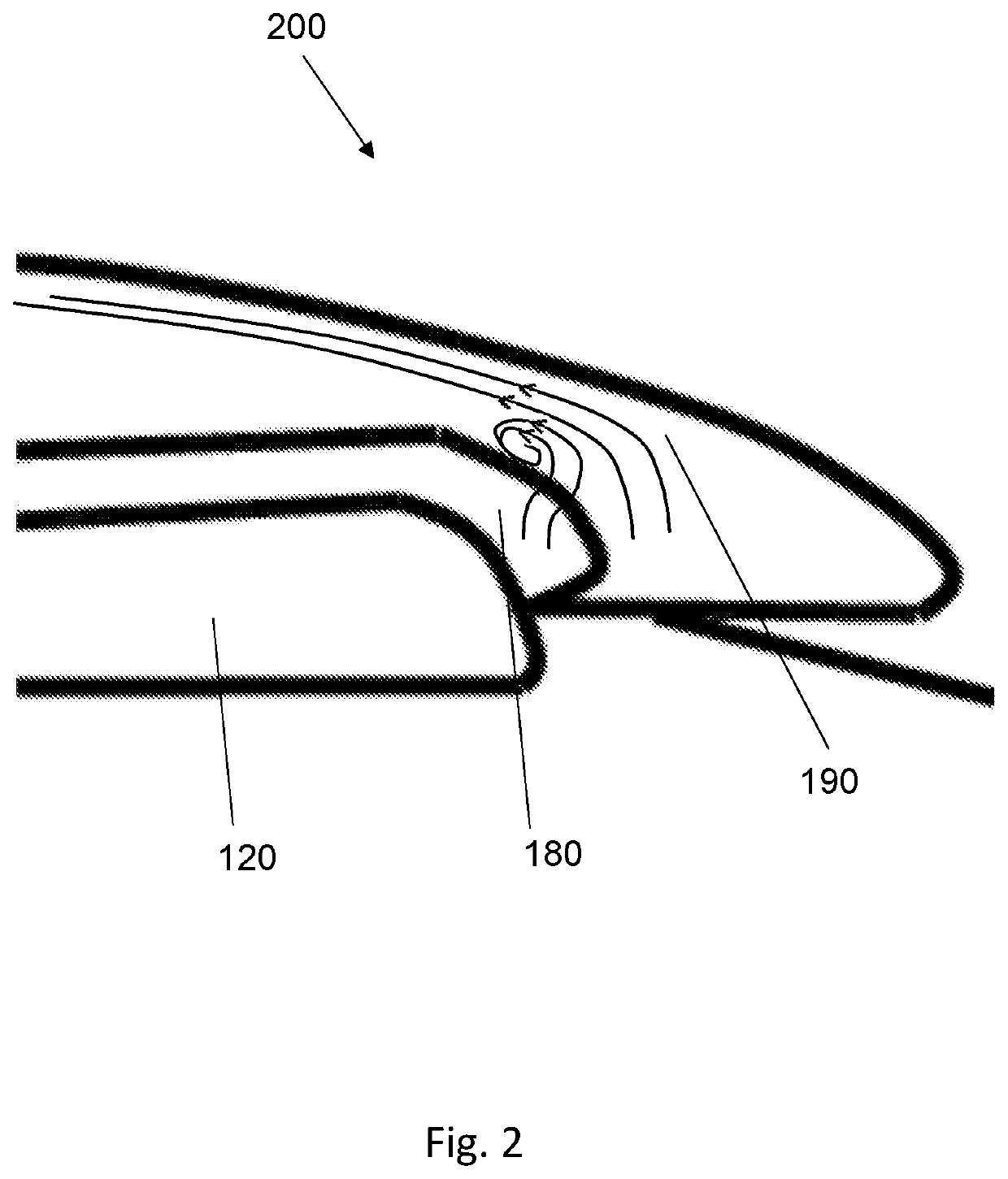
[0046]In the first embodiment, the upper surface of the wing is at a wing root region. For example, the upper surface of the wing may be formed by a wing root fairing. As such, the structure 310 is arranged in the vicinity of a wing root, it being understood that the structure 310 may be arranged on other regions of the wing upper surface in other embodiments.
[0047]The aerodynamic structure 310 is arranged adjacent to the recess edge 330. As such, in the first embodiment, the structure 310 is arranged adjacent to an end face 340 of the slat recess. The structure 310 may abut the recess edge 330, e.g. be in direct contact with the recess edge 330, or may be separated from the recess edge 330 but still be in relatively close proximity to the recess edge 330. The aerodynamic structure 310 is considered to be adjacent to the recess edge 330 in both of the above cases.
[0048]The aerodynamic structure 310 provides the wing upper surface 320 with additional volume and height in the vicinity...
second embodiment
[0062]FIG. 5 shows a diagonal perspective view of an aerodynamic structure 510 applied to an upper surface of a wing, according to a
[0063]In this embodiment, the structure 510 is on the upper surface of the wing adjacent to a junction between an outboard end of a slat and a wing tip region. The wing tip region may include a winglet. The junction forms an exposed recess edge when the slat is deployed. The junction is an example of a wing discontinuity. The structure 510 is arranged to encourage air flowing over the recess edge onto the wing upper surface to remain attached.
third embodiment
[0064]FIG. 6 shows a diagonal perspective view of an aerodynamic structure 610 applied to an upper surface of a wing, according to a
[0065]In this embodiment, the structure 610 is on the upper surface of the wing at a wing pylon region. The pylon region may include a pylon, or station, at which an engine is mounted to the wing. The structure 610 is at a junction between an inboard end of a slat and the wing pylon region. In some cases, the structure 610 is at a junction between an outboard end of a slat and the wing pylon region. The junction forms an exposed recess edge when the slat is deployed. The junction is an example of a wing discontinuity. The structure 610 is arranged to encourage air flowing over the recess edge onto the wing upper surface to remain attached.
PUM
 Abstract
Description
Claims
Application Information
 - R&D
- Intellectual Property
- Life Sciences
- Materials
- Tech Scout
- Unparalleled Data Quality
- Higher Quality Content
- 60% Fewer Hallucinations
Browse by: Latest US Patents, China's latest patents, Technical Efficacy Thesaurus, Application Domain, Technology Topic, Popular Technical Reports.
© 2025 PatSnap. All rights reserved.Legal|Privacy policy|Modern Slavery Act Transparency Statement|Sitemap|About US| Contact US: help@patsnap.com


