System and method for root loss reduction in wind turbine blades

Inactive Publication Date: 2013-06-20
GENERAL ELECTRIC CO
View PDF9 Cites 10 Cited by
  • Summary
  • Abstract
  • Description
  • Claims
  • Application Information

AI Technical Summary

Benefits of technology

[0011]a strake attached to the trailing edge side of the root section, wherein the leading edge extension (LEX) provides both optimal angle of attac

Problems solved by technology

Current manufacturing practices generally prevent the attainment of desired or ideal angles of attack in the root region of wind turbine blades due to constraints on blade twist.
The root region airfoil sections, as a result, are at very high angles of attack

Method used


Image

  • System and method for root loss reduction in wind turbine blades
  • System and method for root loss reduction in wind turbine blades
  • System and method for root loss reduction in wind turbine blades

Examples


Embodiment Construction

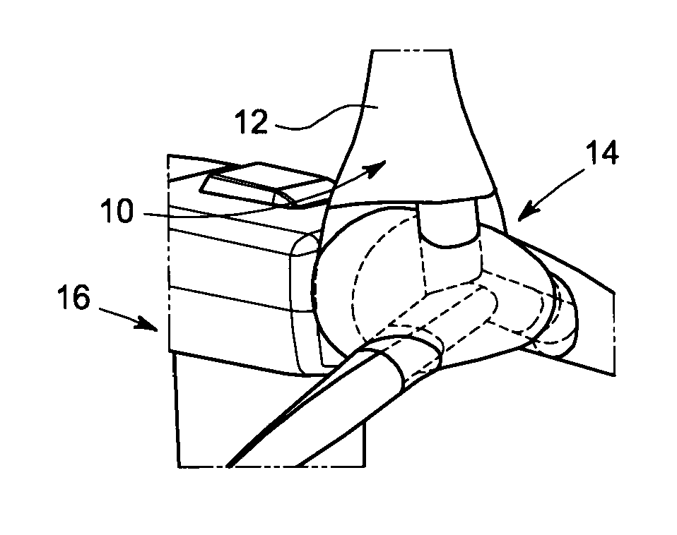
[0028]FIG. 1 is a perspective diagram illustrating the root region 10 of wind turbine blades 12 according to one embodiment. The wind turbine blades 12 are attached to a rotor disk 14 portion of a wind turbine 16.

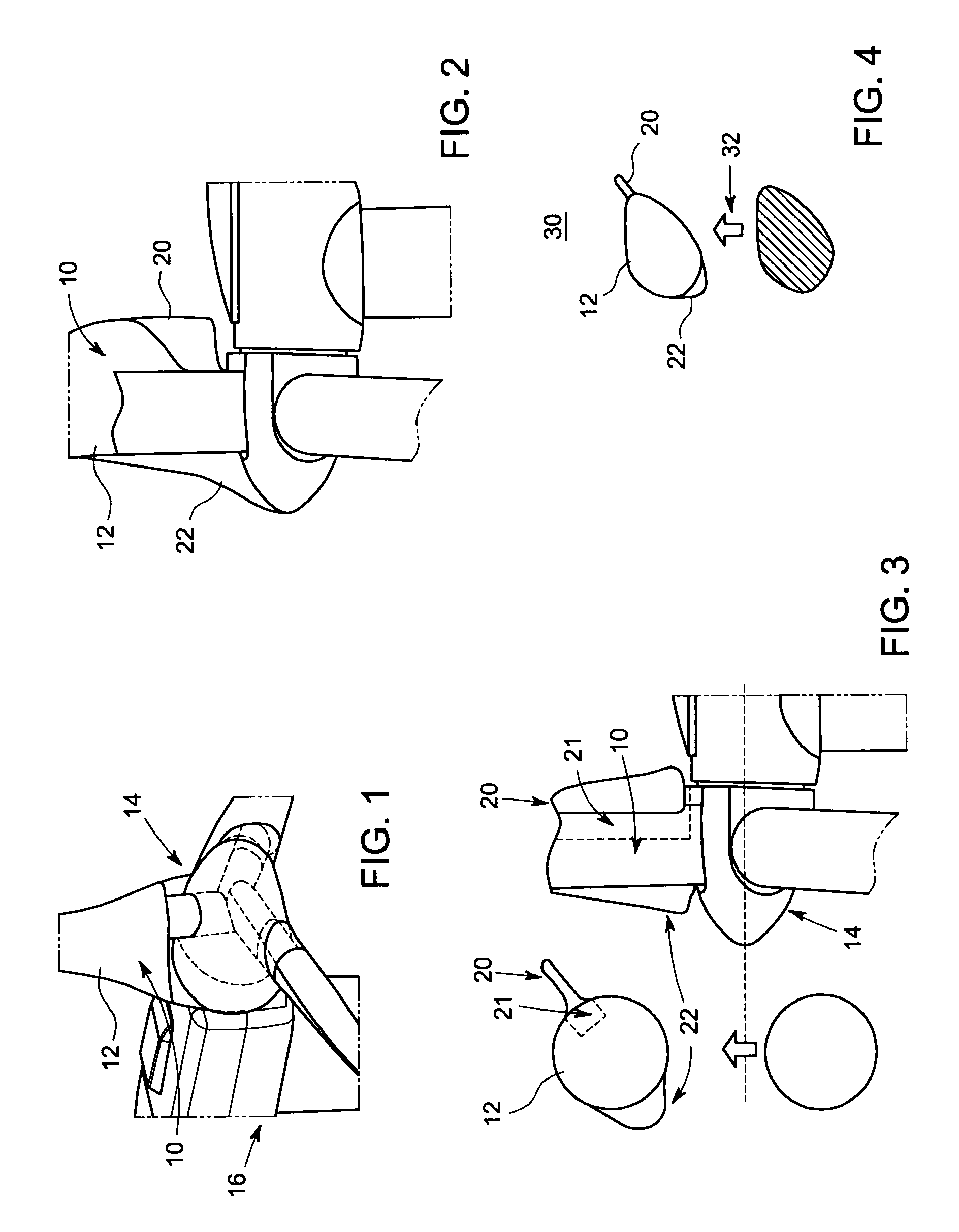
[0029]FIG. 2 is side view illustrating the root region 10 depicted in FIG. 1. Each wind turbine blade 12 has a leading edge extension (LEX) 22 and a trailing edge strake (TES) 20 attached to its corresponding root region 10. The present inventors discovered the combination of a leading edge extension 22 and a trailing edge strake 20 provided a means of reducing aerodynamic losses and enhancing torque extraction from the root section of a wind turbine blade 12.

[0030]FIG. 3 illustrates a root region leading edge extension 20 and a root region trailing edge strake 22 attached to a wind turbine blade 12 according to one embodiment. The LEX 20 is attached to the nose of an existing root airfoil section / region 10 and provides both an optimal incidence angle (angle of attack in a ...


PUM


Abstract

A wind turbine blade includes a root region. A first extension (LEX) is attached to the leading edge side of the root region while a trailing edge strake (TES) is attached to the trailing edge side of the root region. The LEX and TES each include an outer profile that becomes more pronounced relative to their respective locations in the root region as the root region of the wind turbine blade morphs from a substantially cylindrical shape to a substantially airfoil shape. The LEX provides both optimal angle of attack and lift generation in the root region, while the TES mitigates airflow separation and enhances airfoil lift in the root region.

Description

BACKGROUND[0001]The subject matter of this disclosure relates generally to rotor blades for a wind turbine, and more particularly to a leading edge extension (LEX) in combination with a trailing edge strake (TES) as a means of reducing aerodynamic losses and enhancing torque extraction from the root section of a wind turbine blade.[0002]Rotor blades are primary elements of wind turbines for the conversion of wind energy into electrical energy. The working principle of the rotor blades resembles that of airplane wings. A cross-section of a typical blade, during operation thereof, enables air to flow along both sides of the blade producing a pressure difference between the sides. Consequently, a lift force, which is directed from a pressure side towards a suction side, acts on the blade.[0003]In addition, an attached-flow region has a mainly laminar flow along an outer surface area of the blade. In contrast, a detached-flow region in the wake of flow separation has a more turbulent fl...

Claims


Application Information

Patent Timeline
IPC IPC(8): F03D1/06F03D11/00
CPCY02E10/721F05B2240/301F03D1/0633Y02E10/72
Inventor GUPTA, ANURAGGOPINATH, ARATHI KAMATH
Owner GENERAL ELECTRIC CO
Why Eureka
Try Eureka