Coolable airfoil structure

Inactive Publication Date: 2001-05-22
UNITED TECH CORP
View PDF9 Cites 126 Cited by
  • Summary
  • Abstract
  • Description
  • Claims
  • Application Information

AI Technical Summary

Benefits of technology

A primary advantage of the present invention is the durability and thermomechanical performance of the airfoil which results from a spanwisely thinner flow divider having less mass between converging sidewalls for a given amount of diffusion of the different angles of diffusion than a similar construction having equal angles of diffusion (angle of convergence) for the outwardly and inwardly facing sidewalls. Another advantage is the rate of heat transfer which results from the thinner wall of the downstream portion of the flow div

Problems solved by technology

As a result, the airfoils are bathed in hot working medium gases during operation of the rotor blades causing thermal stresses in the airfoils.
These thermal stresses affect the structural integrity and fatigue life of the airfoil.
In addition, rotational forces acting on the rotor blade cause additional stresses in the rotor blade, such as mechanical stresses, as the rotor blade is driven about the axis of rotation.
The use of such a cooling fluid has a negative impact on the aerodynamic efficiency of the

Method used


Image

  • Coolable airfoil structure
  • Coolable airfoil structure
  • Coolable airfoil structure

Examples


embodiment 156

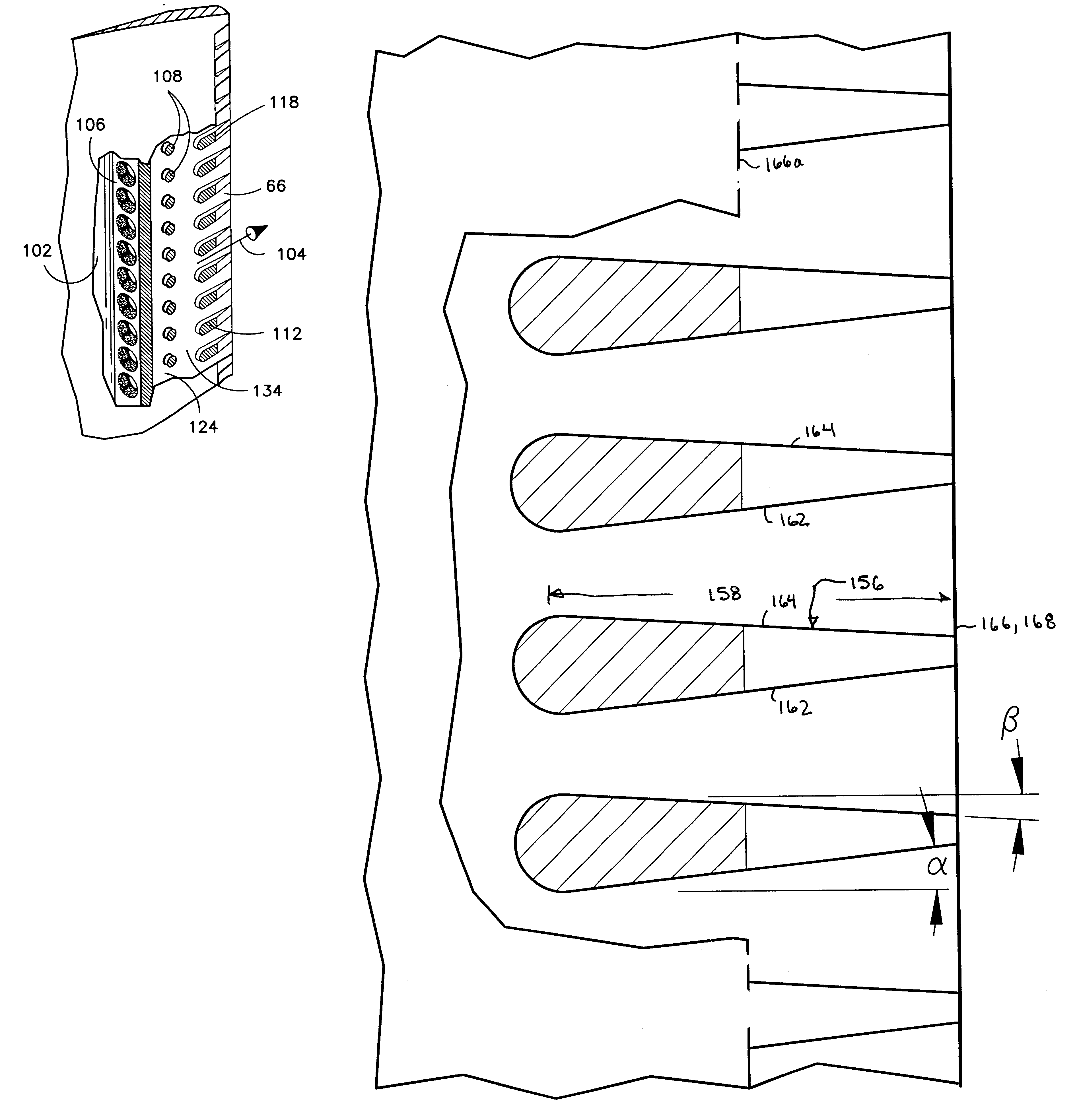
FIG. 8 shows an alternate embodiment 156 of the flow dividers 112 and is shown in a converging diffusing section 158. The pair of converging sidewalls 162,164 are converging in the downstream direction such that spanwisely facing sidewalls of adjacent dividers diverge to define the diffusing section 158 between adjacent dividers. Each flow divider has a first converging sidewall 162 which faces spanwisely inwardly. The first converging sidewall is angled away from the direction of flow between flow dividers with an angle .alpha. as measured with respect to a line parallel to the axis of rotation Ar. In the embodiment shown, the angle .alpha. might also be measured measured with respect to a reference line perpendicular to a spanwise line connecting the centers of the leading edge circle. A second converging sidewall faces spanwisely outwardly. The second converging sidewall is angled away from the direction of flow between flow dividers with an angle .beta. as measured with respect ...

embodiment 170

FIG. 9 is an alternate embodiment 170 of the flow dividers 156 shown in FIG. 8. The flow divider 170 has a constant thickness section 172. The constant thickness section includes a pair of parallel sidewalls 174 which are radially spaced from each other. Each of the parallel sidewalls is also radially spaced from and parallel to a parallel sidewall of an adjacent flow divider. The parallel sidewalls of adjacent flow dividers, in conjunction with the pressure wall and suction wall, define constant area channels 176 of constant width between the flow dividers.

The converging section of the flow dividers includes a pair of converging sidewalls 176, 178. In this embodiment, the angle .alpha.2 of the radially outer flow divider 178o is slightly greater than the angle .alpha.1 if the radially inner flow divider 170i.

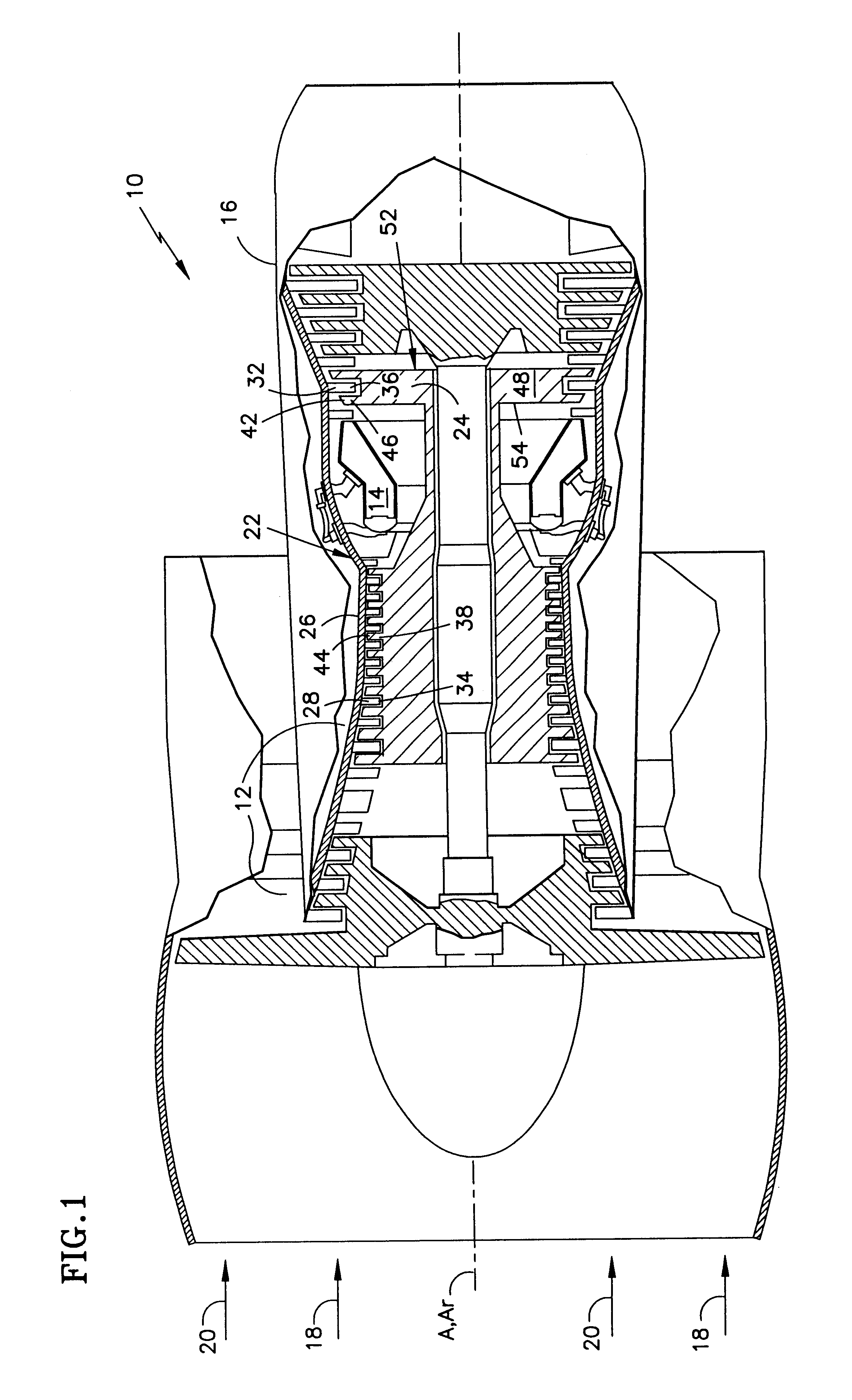
During operation of the gas turbine engine shown in FIG. 1, hot working medium gases are flowed along the working medium flowpath 18 over the airfoil 46. Cooling fluid is flowe...


PUM


Abstract

A coolable airfoil structure having internal heat transfer features through which cooling air is flowed under operative conditions is disclosed. Various construction details and features are developed which affect the castability and core strength during manufacture and strength and cooling effectiveness of the airfoil after manufacture. In one particular embodiment, the airfoil has a plurality of heat transfer members disposed in the rearmost section of the trailing edge region which comprises a single impingement rib, a single row of pedestals and a single row of chordwisely extending flow dividers.

Description

This invention relates to coolable airfoil structures of the type used in high temperature rotary machines, and more specifically, to heat transfer elements in the trailing edge region of such airfoils. The concepts disclosed have application to airfoils for turbine vanes and for turbine bleeds.An axial flow rotary machine, such as a gas turbine engine for an aircraft, has a compression section, a combustion section, and a turbine section. An annular flow path for working medium gases extends axially through the sections of the engine. The gases are compressed in the compression section to raise their temperature and pressure. Fuel is burned with the working medium gases in the combustion section to further increase the temperature of the hot, pressurized gases. The hot, working medium gases are expanded through the turbine section to produce thrust and to extract energy as rotational work from the gases. The rotational work is transferred to the compression section to raise the pre...

Claims


Application Information

Patent Timeline
IPC IPC(8): F01D5/18
CPCF01D5/187B22C9/10Y02T50/673Y02T50/676F05D2230/21F05D2260/2212F05D2260/22141F05D2260/2214Y02T50/60
Inventor ZELESKY, MARK F.MONGILLO, JR., DOMINIC J.
Owner UNITED TECH CORP
Why Eureka
Try Eureka