Method for improvement of the efficiency of a wind turbine rotor

a technology efficiency improvement, which is applied in the direction of wind motors with parallel air flow, non-positive displacement fluid engines, liquid fuel engine components, etc., can solve the problems of increased drag and reduced lift, difficult measurement of mechanical power curve, and aerodynamic noise, so as to improve the efficiency of wind turbine rotor

Inactive Publication Date: 2006-06-13
BONUS ENERGY +1
View PDF6 Cites 120 Cited by
  • Summary
  • Abstract
  • Description
  • Claims
  • Application Information

AI Technical Summary

Benefits of technology

[0012]An object of the present invention is to provide ...

Problems solved by technology

The shedding of the wake and the confluence of flow from the pressure and suction sides of the profile are sources of aerodynamic noise, and increased drag and reduced lift.
The measurement of a mechanical power curve is difficult, however, requiring stable torque instrumentation o...

Method used


Image

  • Method for improvement of the efficiency of a wind turbine rotor
  • Method for improvement of the efficiency of a wind turbine rotor
  • Method for improvement of the efficiency of a wind turbine rotor

Examples


Embodiment Construction

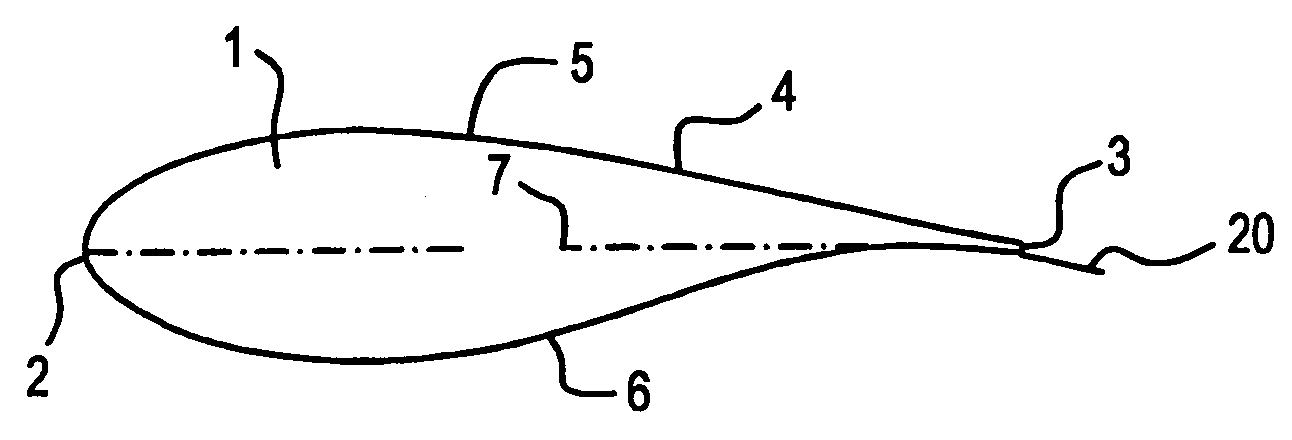
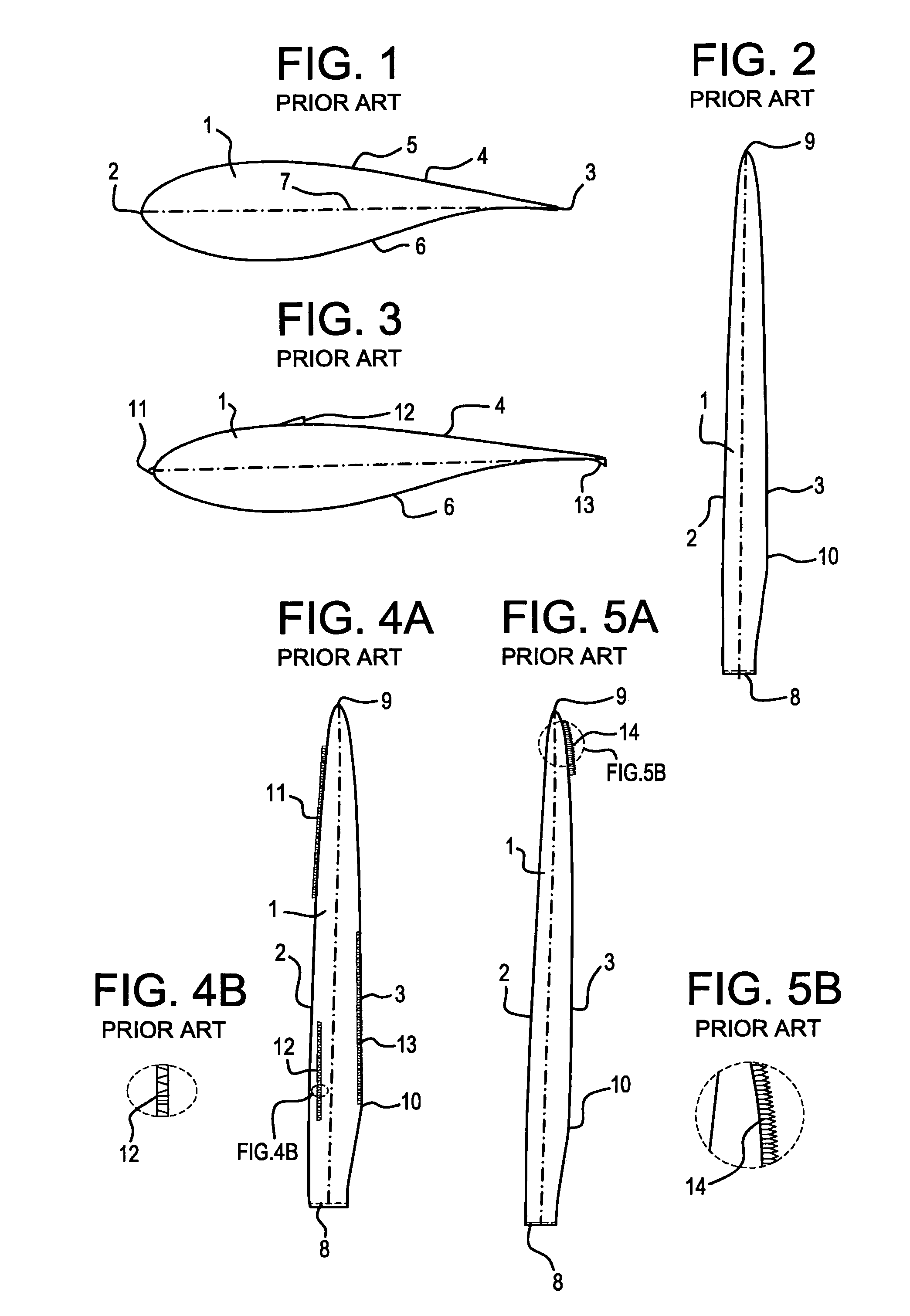
[0030]FIG. 1 shows a schematic cross section of a wind turbine blade 1 having a leading edge 2, a trailing edge 3, and a lifting surface 4 between the leading edge and the trailing edge. The lifting surface has a more convex side 5 referred to as the suction side, and a less convex side6 referred to as the pressure side. A chord 7 is an imaginary line drawn between the leading edge 2 and the trailing edge 3.

[0031]FIG. 2 shows a schematic plan view of a wind turbine blade 1 having a root end 8 and a tip end 9. The length of the blade from root to tip is referred to as a span. Parts of the blade near the tip are referred to as being outboard, and parts of the blade near the root are referred to as being inboard. The outboard part of the blade has an aerodynamically shaped cross-section, commonly with a profile belonging to one of numerous “families” of aerodynamic profiles used in the aeronautic industry. At the inboard part of the blade the aerodynamically shaped cross-section is com...


PUM

PropertyMeasurementUnit
Fractionaaaaaaaaaa
Fractionaaaaaaaaaa
Angleaaaaaaaaaa

Abstract

A method for the improvement of wind turbine rotor efficiency blades of a wind turbine rotor with serrated trailing edges each having a plurality of span-wise, periodic indentations, in the form of saw teeth having approximately 60 degrees included angles between adjacent vertices. The efficiency of an existing wind turbine rotor is improved by the attachment of an apparatus to at least part of the trailing edge of the wind turbine blades, the apparatus being in the form of a serrated panel that is fixed to the surface of the blade and has the serrations extending into the airflow behind the trailing edge of the existing blade. The efficiency of a new wind turbine blade is improved by manufacturing the blade with serrations of at least part of the trailing edge of the wind turbine blade.

Description

BACKGROUND OF THE INVENTION[0001]The present invention relates generally to the field of wind turbine aerodynamics, in particular to the optimizing of the energy output from a wind turbine rotor consisting of a plurality of blades.[0002]Typically, the aerodynamic surfaces of wind turbine blades have sharp or moderately blunt trailing edges from which the wake is shed. The shedding of the wake and the confluence of flow from the pressure and suction sides of the profile are sources of aerodynamic noise, and increased drag and reduced lift.[0003]For a wind turbine rotor of a given diameter it is possible to determine the total mechanical power available at a given wind speed. The efficiency of the wind turbine rotor at a given wind speed is the ratio between the shaft power and the total mechanical power available in the wind at that wind speed.[0004]For everyday purposes the efficiency of a wind turbine rotor is displayed in the so-called power curve of the wind turbine. A power curv...

Claims


Application Information

Patent Timeline
IPC IPC(8): F03D1/06F03D11/00
CPCF03D1/0641F03D11/00F05B2240/301F05B2240/31F05B2240/311Y10T29/49336Y02E10/722F05B2260/96Y10T29/49332Y10T29/49327Y02E10/721F03D80/00Y02E10/72Y02P70/50
Inventor STIESDAL, HENRIKENEVOLDSEN, PEDER BAY
Owner BONUS ENERGY
Why Eureka
Try Eureka