Tandem isotachophoresis/zone electrophoresis method and system

a technology of isotachophoresis and electrophoresis, applied in the direction of fluid speed measurement, electrolysis, diaphragm, etc., can solve the problems of large sample volume and poor resolution of sample components

Inactive Publication Date: 2009-02-24
MONOGRAM BIOSCIENCES
View PDF19 Cites 118 Cited by
  • Summary
  • Abstract
  • Description
  • Claims
  • Application Information

AI Technical Summary

Problems solved by technology

Efficient electrophoretic injection of dilute samples frequently results in large sample volumes and poor resolution of the sample components.

Method used


Image

  • Tandem isotachophoresis/zone electrophoresis method and system
  • Tandem isotachophoresis/zone electrophoresis method and system
  • Tandem isotachophoresis/zone electrophoresis method and system

Examples


Embodiment Construction

I. Microfluidic System

[0039]The invention includes, in one aspect, a microfluidic system for use in electrophoretic separation of components having a given negative or positive charge and contained in a dilute sample. By “sample” is meant an aqueous sample containing one or more charged components which can be separated electrophoretically, and preferably detected by standard optical techniques applicable to capillary zone electrophoresis. By “dilute sample” is meant a sample in which at least one of the components to be separated and detected is present at a concentration as low as 100 fM (femptomolar), typically 1 pM (picomolar) to higher concentrations, e.g., several hundred nanomolar of higher, preferably in the 1-500 pM range.

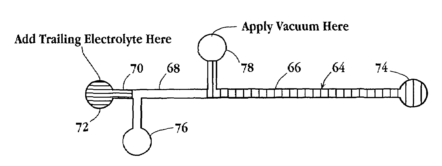
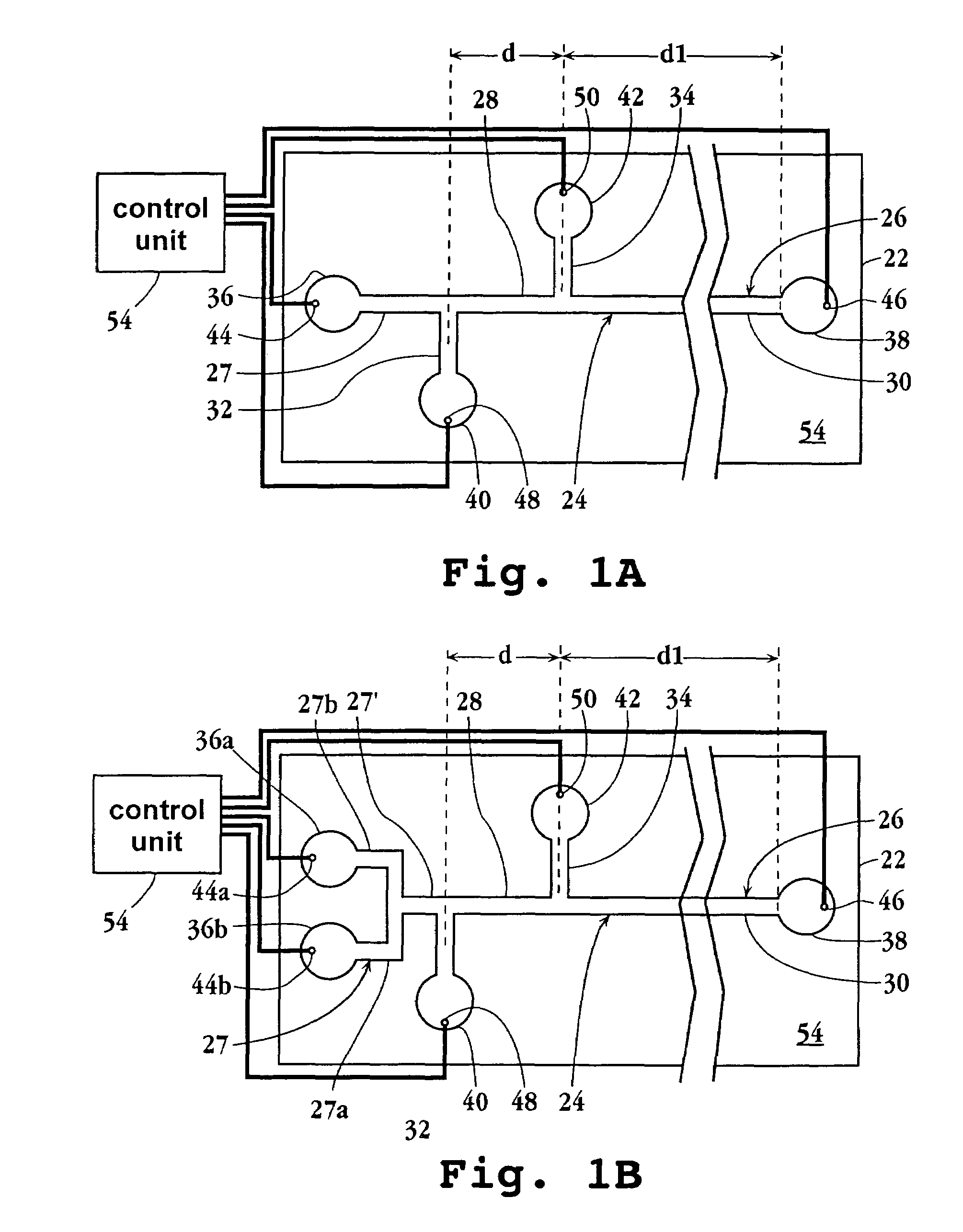
[0040]One exemplary system in accordance with the invention is shown at 22 in FIG. 1. The system includes a microfluidics device 24 having formed therein one or more channel networks, such as network 26 composed of a separation microchannel 26 having, in a...


PUM

PropertyMeasurementUnit
thicknessaaaaaaaaaa
thicknessaaaaaaaaaa
thicknessaaaaaaaaaa

Abstract

A method of separating components having a given negative or positive charge and contained in a sample is disclosed. The method involves, in one embodiment, loading a microchannel with a sample, placed between a trailing-edge electrolyte having a selected concentration of a titratable species, and a leading-edge electrolyte. With the application of a voltage potential across the microchannel, charged components in the sample stack by isotachophoresis, and electrolytic hydroxyl or hydrogen ions formed by electrolysis at the upstream-end electrode migrate into the trailing-edge ion buffer, titrating the titratable species therein, where the concentration of the titratable species in the trailing-edge electrolyte is selected , in relation to the lengths of the upstream channel region and sample-loading volume, to permit the sample to stack into a relatively small sample volume before electrolytic-ion migration from the upstream electrode into and through the sample-volume region is effective to overtake the charge sample components. With continued application of an electric potential across the channel ends, charged sample components in the stacked sample volume separated by zone electrophoresis.

Description

[0001]This application is a divisional of U.S. Ser. No. 09 / 933,993, filed Aug. 20, 2001, now U.S. Pat. No. 6,685,813 which is a continuation-in-part of U.S. Ser. No. 09 / 780,638, filed Feb. 10, 2001, now U.S. Pat. No. 6,818,113 which in turn claims priority to U.S. provisional patent applications Ser. No. 60 / 182,049 filed Feb. 11, 2000 and Ser. No. 60 / 185,035, filed Feb. 25, 2000, all of which are incorporated herein by reference.FIELD OF THE INVENTION[0002]The field of this invention is related to sample loading, stacking, and separation in a microfluidics device.BACKGROUND[0003]Microfluidics is revolutionizing the way activities are performed in a substantial proportion of chemical and physical operations. One area of microfluidics is the manipulation of small volumes of liquids or liquid compositions on a solid substrate, where a network of channels and reservoirs are present. By employing electric fields with electrically conducting liquids, volumes and / or ions can be moved from ...

Claims


Application Information

Patent Timeline
Patent Type & Authority Patents(United States)
IPC IPC(8): G01N27/447B01D57/02B01L3/00B03C5/00B81B1/00C07K1/26C07K1/28C08F2/58G01N37/00
CPCB01L3/5027B01L3/502753C07K1/26C07K1/28G01N27/44773B01L2200/0605B01L2300/0816B01L2400/0415B01L2400/0421B01L2400/049
Inventor WILLIAMS, STEPHEN J.TAN, HONG DONGKAO, HUNG PINVREELAND, WYATT N.
Owner MONOGRAM BIOSCIENCES
Why Eureka
Try Eureka