Centrifugal fluid pump

A hydraulic pump, centrifugal technology, applied in the field of centrifugal hydraulic pumps

Inactive Publication Date: 2010-11-10
GM GLOBAL TECH OPERATIONS LLC
View PDF6 Cites 11 Cited by
  • Summary
  • Abstract
  • Description
  • Claims
  • Application Information

AI Technical Summary

Problems solved by technology

The result is the creation of vapor bubbles in the fluid

Method used


Image

  • Centrifugal fluid pump
  • Centrifugal fluid pump
  • Centrifugal fluid pump

Examples


Embodiment Construction

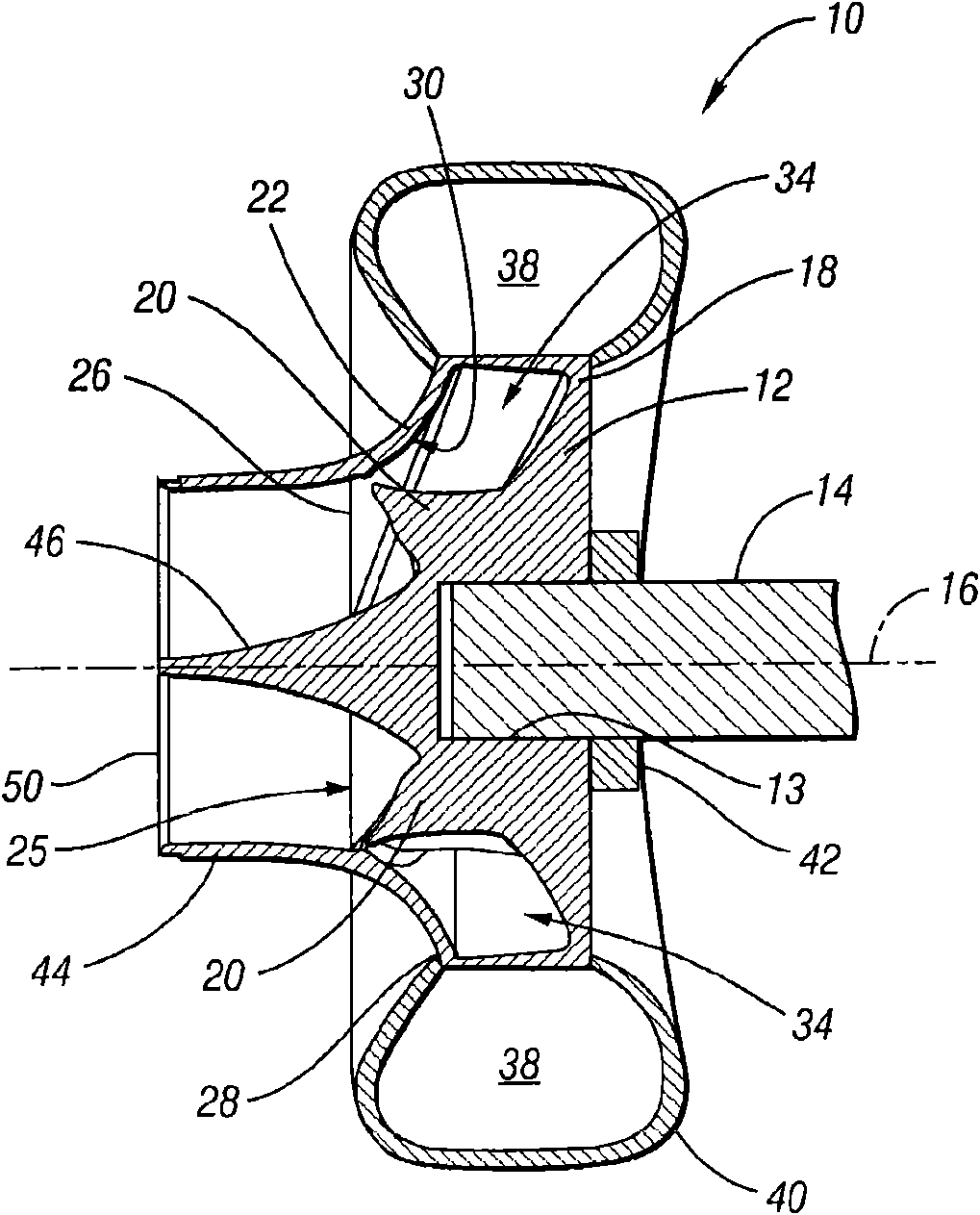
[0046] Referring to the drawings, the same reference numerals in the figures represent the same parts, figure 1Shown is a centrifugal hydraulic pump 10, in this embodiment a water pump for an automobile engine, but is not limited thereto. The pump 10 includes an impeller 12 mounted to a rotatable shaft 14 at a central cavity 13 . The shaft 14 is rotatably driven about an axis of rotation 16 . Shaft 14 may be mechanically driven, such as by gears or belts coupled to the engine crankshaft or camshaft as is known. Alternatively, the shaft 14 may be driven by an electric motor powered using a power source, such as a standard 12 volt battery.

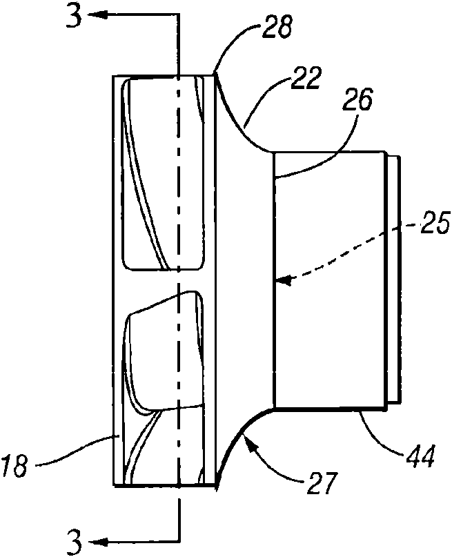
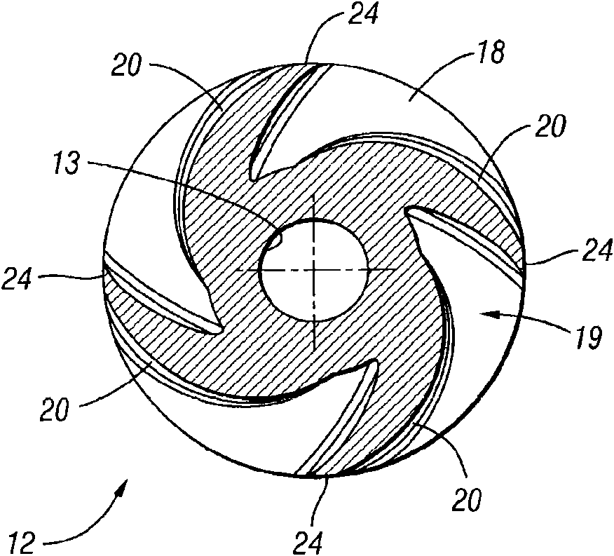
[0047] see image 3 , the impeller 12 includes the hub 18, when such as figure 1 As shown installed, the hub 18 is coaxial with the shaft 14 . The hub 18 has a surface 19 from which the impeller blades 20 protrude. The hub 18 and blades 20 may be die-cast, injection-molded, or otherwise formed as an integral part. If the hub 18 and ...


PUM


Abstract

A centrifugal fluid pump has an impeller having a hub with vanes that may be airfoil shaped and may be twisted along their lengths. A shroud having an inlet is connected to the vanes to define with the impeller flow chambers between the vanes, at least a portion of each flow chamber having a substantially constant flow area to increase pump efficiency. An entrance feature may also be provided to improve entrance flow into the impeller, further enhancing pump efficiency.

Description

[0001] CROSS-REFERENCE TO RELATED APPLICATIONS [0002] This application claims priority to US Provisional Patent Application No. 61 / 176,559, filed May 8, 2009, the entire contents of which are incorporated herein by reference. technical field [0003] The invention relates to a centrifugal hydraulic pump. Background technique [0004] Shaft-driven centrifugal impeller pumps are often used to cool automotive engines. Water or other fluid is introduced into the pump axially and discharged radially into one or more volutes. The shaft is usually mechanically driven directly or indirectly by the engine crankshaft and thus rotates at some speed proportional to the engine speed. Pump design affects pump efficiency. Increased pump efficiency means less power is consumed to drive the pump and can result in improved fuel economy. Less-than-ideal fluid flow results in fluid separation in the flow field, reducing pump capacity and possibly causing unwanted pump noise due to cavita...

Claims


Application Information

Patent Timeline
Patent Type & Authority Applications(China)
IPC IPC(8): F04D29/24F04D1/04F04D29/42
Inventor A·R·扎德
Owner GM GLOBAL TECH OPERATIONS LLC
Why Eureka
Try Eureka