Four-way hydraulic transformer with axial flow distribution structure

A four-way hydraulic and shaft distribution technology, applied in the field of hydraulic components, can solve the problems affecting the balance of the distribution plate, increase the friction of the distribution surface, and the volume of the distribution structure, so as to improve the service life, reduce the axial impact, and improve the volumetric efficiency. Effect

Active Publication Date: 2021-02-19
XUZHOU NORMAL UNIVERSITY
View PDF6 Cites 0 Cited by
  • Summary
  • Abstract
  • Description
  • Claims
  • Application Information

AI Technical Summary

Problems solved by technology

Since there are four distribution oil holes on the flow distribution plate of the four-way hydraulic transformer and each oil hole needs to be supplied with oil separately, it is difficult to arrange the flow channels when the traditional distribution plate and the rear end cover plane friction distribution method are used. When changing the transformation ratio, the flow area between the distribution plate and the rear end cover gradually decreases, resulting in throttling loss, and the rotation angle range is limited, resulting in the limitation of the transformation range of the four-way transformer.
[0004] The existing integrated hydraulic transformer often adopts a plane friction pair flow distribution structure in the cooperation between the distribution plate and the rear end cover. There are multiple large-angle arc-shaped grooves opposite to each other on the two planes. It is difficult to adopt other effective sealing methods, and the leakage is serious; as the rotation angle of the distribution plate increases, the flow area between the distribution plate and the rear end cover gradually decreases, and serious throttling losses will occur, reducing the hydraulic transformer. Efficiency, in order to ensure the effective flow area, the rotation angle range can only be further limited, so the pressure transformation range is small; some rear end covers and distribution plate slots adopt an asymmetric design, and different arc slots are distributed in different positions. In terms of radius, the flow area and rotation range are guaranteed, but the too long arc-shaped groove makes the radial impact force on the distribution plate when the rear end cover enters oil is large, which affects the balance of the distribution plate and increases the friction of the distribution surface. The service life of the hydraulic transformer is reduced; and the existing distribution structure generally has problems such as large volume, large mass, and serious leakage, which need further improvement

Method used


Image

  • Four-way hydraulic transformer with axial flow distribution structure
  • Four-way hydraulic transformer with axial flow distribution structure
  • Four-way hydraulic transformer with axial flow distribution structure

Examples


Embodiment 1

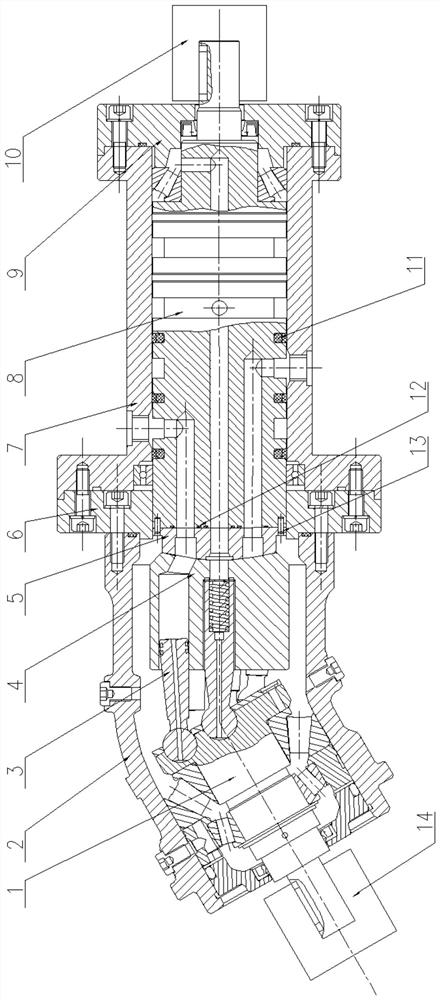
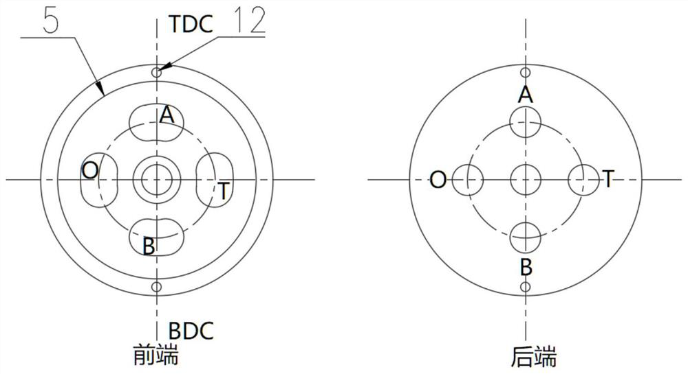
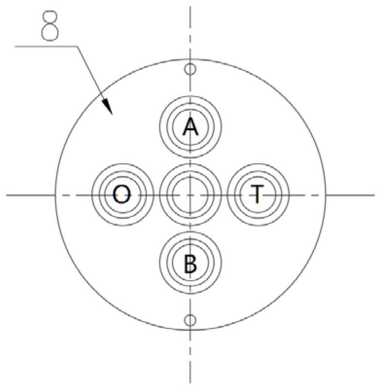
[0017] Such as figure 1 As shown, a distribution shaft type four-way hydraulic transformer includes a main shaft 1; a hydraulic transformer housing 2; a plunger 3; a cylinder body 4; a distribution plate 5; a transition plate 6; End cover 9; servo motor 10; rotary gray ring 11; O-shaped sealing ring 12; pin shaft 13; rotary encoder 14. The main shaft 1, the plunger 3 and the cylinder body 4 are fixed in the transformer housing 2 through bearings. One end of the cylinder body 4 is bonded to the front end of the valve plate 5 through the oil film. There are four waist-shaped grooves 5-1 on the valve plate 5, and the valve plate The center of the waist-shaped groove 5-1 is provided with a through-distribution plate flow channel 5-2, and the inside of the distribution shaft 8 is provided with a corresponding distribution shaft flow channel 6-1. The sealing connection ensures that the distribution plate 5 is coaxial with the distribution shaft 8 and the internal flow passages (5-2...


PUM


Abstract

The invention discloses an axial flow distribution type four-way hydraulic transformer. The transformer comprises a main shaft, a hydraulic transformer shell, a plunger, a cylinder body, a flow distribution plate, a transition plate, a flow distribution shaft shell, a flow distribution shaft, a rear end cover, a servo motor and a rotary Glyd ring. Four kidney-shaped grooves are formed in the flowdistribution plate, a through flow distribution plate flow channel is formed in the center of each kidney-shaped groove of the flow distribution plate, flow distribution shaft flow channels corresponding to the flow distribution plate flow channels are formed in the flow distribution shaft, the rear end of the flow distribution plate is connected with the flow distribution shaft in a sealed mode through a pin, the flow distribution plate is coaxial with the flow distribution shaft, and the flow channels in the flow distribution plate and the flow distribution shaft sequentially and correspondingly communicate; and four fully-circumferential annular grooves are formed in the flow distribution shaft and sequentially communicate with the internal flow distribution shaft flow channels. According to the shaft flow distribution type four-way hydraulic transformer, a through-flow area between the flow distribution shaft and a sleeve is kept constant, and a rotating angle of the flow distribution disc is not limited by throttling loss. The flow distribution grooves are of full-circumference structures, so that the flow distribution shaft is subjected to uniform hydraulic acting force, andaxial impact is reduced. The flow distribution grooves are isolated by coaxial sealing rings, so that the overall volume efficiency of the hydraulic transformer is improved.

Description

technical field [0001] The invention belongs to the technical field of hydraulic components, and in particular relates to an axial distribution type four-way hydraulic transformer. Background technique [0002] Most of the existing integrated hydraulic transformers have a one-to-one correspondence between load pressure and load flow, that is, they cannot meet the controllable flow rate under a specific load pressure. Therefore, the application of existing hydraulic transformers is mostly based on the secondary regulation system of constant voltage network, which cannot Connected in series to the valve-controlled load system. Most of the existing construction machinery adopts the valve-controlled load system, which is very mature, and many of them are made into integrated valve groups and industrial hydraulic pumps that match specific loads. It is difficult to change the structure and process of the existing hydraulic system. . [0003] The new four-way hydraulic transforme...

Claims


Application Information

Patent Timeline
IPC IPC(8): F15B3/00F15B21/00
CPCF15B3/00F15B21/00
Inventor 张楚周连佺薄晓楠刘强瞿炜炜
Owner XUZHOU NORMAL UNIVERSITY
Why Eureka
Try Eureka