Novel vortex generator for wind turbine blade

A technology of vortex generators and wind turbine blades, which is applied in the directions of wind power generators, wind power generation, and wind power engines in the same direction as the wind. The structure is weak and other problems, to achieve the effect of suppressing the three-dimensional flow of the blade root, the shape resistance is small, and the three-dimensional flow is suppressed

Inactive Publication Date: 2019-08-16
SHANGHAI ELECTRIC WIND POWER GRP CO LTD
View PDF4 Cites 7 Cited by
  • Summary
  • Abstract
  • Description
  • Claims
  • Application Information

AI Technical Summary

Problems solved by technology

[0003] There is an included angle between the existing vortex generator and the flow direction. Due to the existence of the included angle, the projection of the fins perpendicular to the flow direction is increased, and the shape resistance is increased. Since the ribs of the vortex generator are "eight" The font layout will lead to an increase in the drag coefficient of the airfoil, thereby affecting the overall power enhancement effect of the vortex generator
However, if there is no such included angle, the airflow passes over the fins of the vortex generator in parallel, and the downstream vortex structure induced by the fins is very weak, the disturbance to the wake is very limited, and the effect of suppressing flow separation is not good
Moreover, in the existing vortex generator, the wingtip vortex induced by a single fin is limited. To induce enough wingtip vortex, the height of the fin needs to be increased. With the increase of the fin height, the resistance introduced by the vortex generator also increases. increases accordingly, and finally limits the maximum lift-to-drag ratio of the airfoil to a certain extent

Method used


Image

  • Novel vortex generator for wind turbine blade
  • Novel vortex generator for wind turbine blade
  • Novel vortex generator for wind turbine blade

Examples


Embodiment Construction

[0030] The present invention will be further described below through specific embodiments with reference to the accompanying drawings. These embodiments are only used to illustrate the present invention and do not limit the protection scope of the present invention.

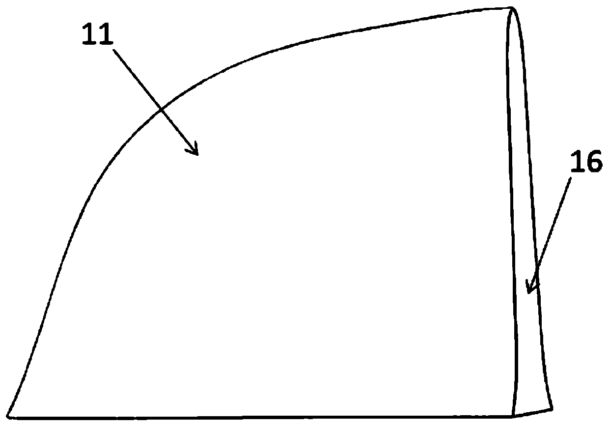
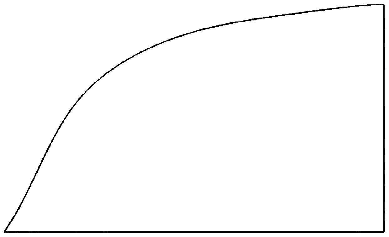
[0031] Such as figure 2 with image 3 As shown, the present invention provides a novel vortex generator 10 for a wind turbine blade 20, which includes a fin body 11; the fin body 11 is a dorsal fin structure and is symmetrical with respect to its middle longitudinal section 12; The middle longitudinal section 12 is parallel to the flow direction of the leading edge 23 to the trailing edge 24 of the wind turbine blade airfoil section 26 where the vortex generator 10 is located, so as to reduce the projected area of ​​the fin body 11 perpendicular to the air flow direction , Thereby reducing the shape resistance.

[0032] Such as Figure 4 As shown, in one embodiment, the fin body 11 includes a bottom surface 13 and tw...


PUM


Abstract

The invention discloses a novel vortex generator for a wind turbine blade. The vortex generator comprises a fin body, wherein the fin body is of a back fin structure and is symmetrical relative to thelongitudinal cross section of the fin body; the middle longitudinal section is parallel to the flow direction from the leading edge to the trailing edge of the airfoil section of the wind turbine blade, so that the projection area of the fin body in the direction perpendicular to the flowing direction is reduced, and then the shape resistance is reduced. According to the vortex generator, the bionic design is adopted, and the back fin-shaped fin body has relatively small flow resistance. The middle longitudinal section of the back fin is parallel to the flow direction from the leading edge tothe trailing edge of the airfoil section of the wind turbine blade, compared with the prior art, the fin body has the advantages that the projection area is small in the direction perpendicular to the flow direction of the airflow, and the shape resistance is small. When the airflow flows through a groove, a high-energy flow direction vortex can be induced at the groove and at the edge of the groove, so that the energy in the boundary layer can be increased, and the flow separation is inhibited.

Description

Technical field [0001] The invention relates to the technical field of wind power equipment, in particular to a new type of vortex generator for wind power blades. Background technique [0002] Several vortex generators are usually installed on the blades of modern wind turbines to generate high-energy wingtip vortices, inhibit flow separation on the upper surface of the airfoil, delay stall, and increase power generation. Common vortex generator structures such as figure 1 As shown, it includes two symmetrically distributed fins and a base. The fins are usually perpendicular to the base and form a certain angle with the flow direction. The geometry of the vortex generator generates a wingtip "vortex" in the flow field similar to that of an airplane wingtip. The wingtip "vortex" rotates to bring the energy of the high-speed fluid outside the boundary layer into the boundary layer, increasing the boundary layer to overcome The ability of the reverse pressure gradient delays the s...

Claims


Application Information

Patent Timeline
Patent Type & Authority Applications(China)
IPC IPC(8): F03D1/06
CPCF03D1/0675F05B2240/30F05B2240/3062Y02E10/72
Inventor 艾国远李海涛
Owner SHANGHAI ELECTRIC WIND POWER GRP CO LTD
Why Eureka
Try Eureka