
power line rack

A technology of power lines and carriages, applied in the direction of electrical components, etc., can solve problems such as inability to erect and limited number of erected power cables

Active Publication Date: 2020-10-23
HEBI POWER SUPPLY OF HENAN ELECTRIC POWERCORP
View PDF1 Cites 0 Cited by
  • Summary
  • Abstract
  • Description
  • Claims
  • Application Information

AI Technical Summary

Problems solved by technology

[0003] The object of the present invention is to provide a power line rack, whose beneficial effect is that the present invention solves the problem that it cannot be erected on sloped or uneven ground or hillsides, and the number of erected power cables is limited

Method used


Image

  • power line rack
  • power line rack
  • power line rack

Examples


specific Embodiment approach 1

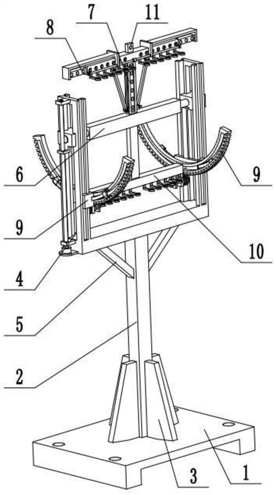
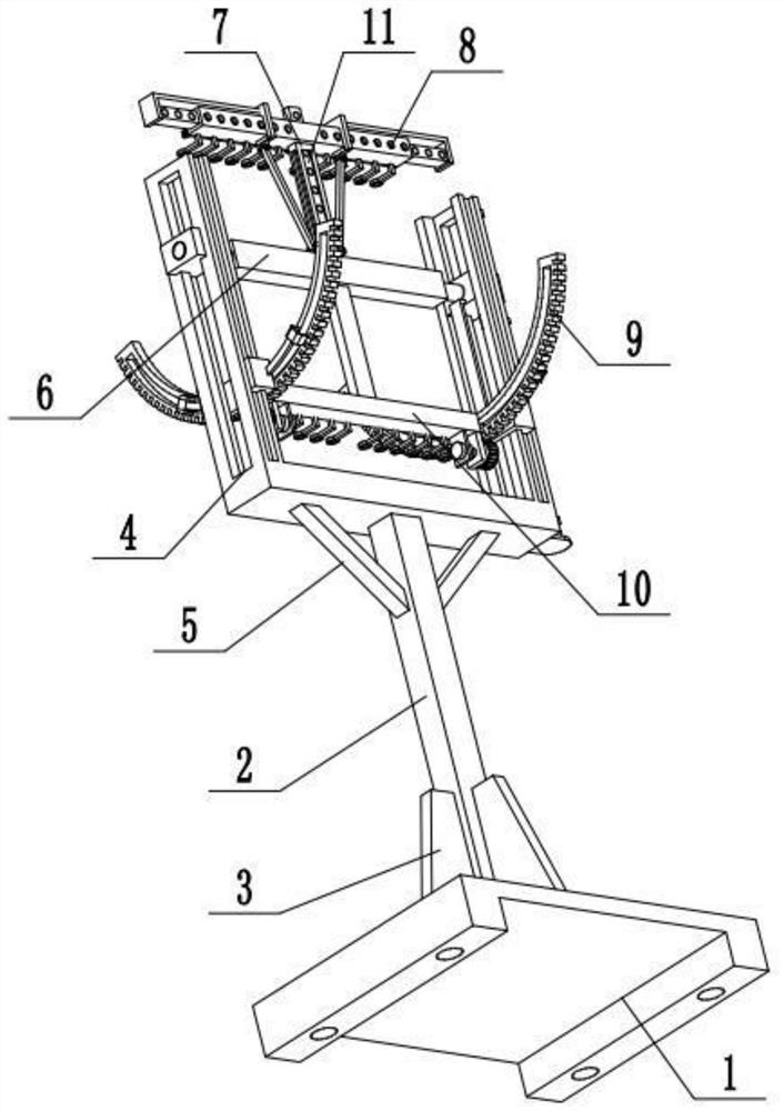
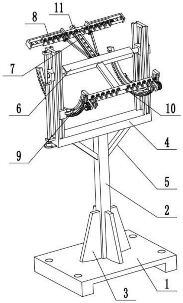
[0032] Combine below Figure 1-14 Describe this embodiment, a power line rack, including a base 1, a support rod 2, a rib plate 3, a height adjustment carriage 4, a diagonal rod 5, a height adjustment seat 6, a support slide frame 7, an upper fixing line assembly 8, an angle Adjust the sliding seat 9, the lower thread fixing assembly 10 and the auxiliary thread fixing assembly 11, the support rod 2 is fixedly connected to the base 1, the height adjustment carriage 4 is fixedly connected to the support rod 2, and the height adjustment seat 6 is slidably connected On the height adjustment carriage 4, the upper end of the height adjustment seat 6 is fixedly connected to the support slide frame 7, the upper wire fixing assembly 8 is fixedly connected to the support slide frame 7, the lower end of the height adjustment seat 6 is fixedly connected to the lower wire fixing assembly 10, and the lower end of the height adjustment seat 6 is fixedly connected to the lower wire fixing asse...

specific Embodiment approach 2

[0034] Combine below Figure 1-14 To illustrate this embodiment, the power line rack described further includes ribs 3 and oblique rods 5; the connection between the support rod 2 and the base 1 is uniformly surrounded and fixedly connected to four ribs 3, and the lower ends of the two oblique rods 5 are symmetrically fixed Connected to the support rod 2, the upper ends of the two oblique rods 5 are all fixedly connected to the height adjustment carriage 4. Four ribs 3 and two slanting rods 5 are used to increase the stability of the device, making the device more suitable for application environments.

specific Embodiment approach 3

[0036] Combine below Figure 1-9 To illustrate this embodiment, the height adjustment carriage 4 includes a bottom plate 4-1, a side plate 4-2, a side block chute 4-3, a rectangular through groove 4-4, a side chute 4-5, a motor I 4- 6. The lead screw 4-7 and the side frame plate 4-8; the bottom plate 4-1 is fixedly connected to the support rod 2, and the two ends of the bottom plate 4-1 are respectively fixedly connected to a side plate 4-2, and two side plates 4- A side block chute 4-3 is respectively arranged on the inner side of the 2, and a rectangular through groove 4-4 is respectively arranged on the two side plates 4-2; the rectangular through groove 4-4 and the side block chute 4-3 connected; the front and rear ends of the side plate 4-2 are respectively provided with a side chute 4-5; The plates 4-8 are all fixedly connected to the left side plate 4-2, the motor I4-6 is fixedly connected to the left side plate 4-2 through the motor frame, and the output shaft of the ...


PUM


Abstract

The invention relates to a power line frame and relates to the technical field of power devices. The power line frame comprises a base, a support rod, a rib plate, a height adjustment carriage, a diagonal rod, a height adjustment seat, a support sliding frame, an upper line fixing component, angle adjustment sliding seats, and a lower line fixing component and an auxiliary line fixing component, and solves the problem that power cables cannot be installed on a sloped or uneven ground or a hillside, the number of installed power cables is limited. The support rod is fixedly connected to the base. The height adjustment carriage is fixedly connected to the support rod. The height adjustment seat is slidably connected to the height adjustment carriage. The upper end of the height adjustment seat is fixedly connected to the support sliding frame. The upper line fixing component is fixedly connected to the support sliding frame. The lower end of the height adjustment seat is fixedly connected to the lower line fixing component. The two ends of the lower line fixing component are slidably connected to the two angle adjustment sliding seats respectively. The two angle adjustment sliding seats are symmetrically and slidably connected to the height adjustment carriage, and are fixedly connected to the height adjustment seat.

Description

technical field [0001] The invention relates to the technical field of power devices, in particular to a power line rack. Background technique [0002] The existing patent number is CN201621317166.7, which is a conveniently adjustable power line support. This utility model provides a conveniently adjustable power line support, which relates to the field of electric power. The easy-to-adjust power line support includes an operation panel, the top of the operation panel is fixedly connected with a first riser and a second riser, the first riser is located behind the second riser, and the top of the operation panel A motor is fixedly installed, and the motor is located between the first vertical board and the second vertical board, the left side of the first vertical board is fixedly connected with the first threaded pipe, and the right side of the second vertical board is fixedly connected with the second Two threaded pipes, the motor is provided with a rotating shaft, the su...

Claims


Application Information

Patent Timeline
Patent Type & Authority Patents(China)
IPC IPC(8): H02G3/04
CPCH02G3/0456
Inventor 鞠玲
Owner HEBI POWER SUPPLY OF HENAN ELECTRIC POWERCORP
Learn More