MRI method for t1 mapping of the heart using a maximum likelihood reconstruction in k-space

A maximum likelihood, cardiac technique, applied in the field of magnetic resonance data acquisition, which can solve problems such as effective local magnetic field disturbance

Active Publication Date: 2019-08-09
KONINKLJIJKE PHILIPS NV
View PDF8 Cites 2 Cited by
  • Summary
  • Abstract
  • Description
  • Claims
  • Application Information

AI Technical Summary

Problems solved by technology

The additionally applied gradient field and B1 field cause a perturbation of the effective local magnetic field

Method used


Image

  • MRI method for t1 mapping of the heart using a maximum likelihood reconstruction in k-space
  • MRI method for t1 mapping of the heart using a maximum likelihood reconstruction in k-space
  • MRI method for t1 mapping of the heart using a maximum likelihood reconstruction in k-space

Examples


Embodiment Construction

[0094] In the figures, like numbered elements are equivalent elements or perform the same function. Elements that have been discussed previously will not necessarily be discussed in subsequent figures if the function is equivalent.

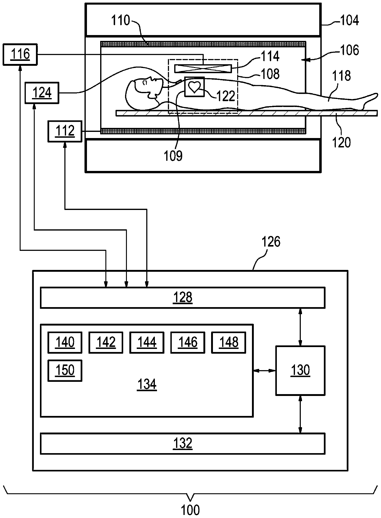
[0095] figure 1 An example of a magnetic resonance imaging system 100 with a magnet 104 is shown. Magnet 104 is a superconducting cylindrical magnet having a bore 106 therethrough. It is also possible to use different types of magnets; for example split cylindrical magnets and so-called open magnets can also be used. A split cylindrical magnet is similar to a standard cylindrical magnet, except that the cryostat has been split into two parts to allow access to the isoplane of the magnet so that the magnet can be used, for example, in conjunction with charged particle beam therapy. An open magnet has two magnet parts, one above the other, with a space in between large enough to accommodate the object: the arrangement of the two part areas is sim...


PUM


Abstract

The invention provides for a magnetic resonance imaging system (100) for acquiring magnetic resonance data (146) from a subject (118) from a region of interest (109) within an imaging zone (108). Themagnetic resonance imaging system comprises a memory (134) for storing machine executable instructions (140) and pulse sequence commands (142). The pulse sequence commands are configured for controlling the magnetic resonance imaging system to perform magnetization preparation pulses which causes magnetization inversion within the region of interest and initiates a T1 relaxation process. The pulsesequence commands are configured for acquiring portions of the magnetic resonance data as discrete units during a rest and relaxation interval of a heart phase of the subject. The magnetic resonanceimaging system further comprises a processor (130) for controlling the magnetic resonance imaging system. Execution of the machine executable instructions causes the processor to repeatedly: receive (202) an ECG signal (124) descriptive of the heart phase of the subject; detect (204) an onset of the rest and relaxation interval of the heart phase using the ECG signal; acquire (206) a portion (146)of the magnetic resonance data a predetermined delay after the onset of the rest and relaxation interval by controlling (200) the magnetic resonance imaging system with the pulse sequence commands, wherein the portion of the magnetic resonance data undersamples k-space; determine (208) an inversion delay (308, 502) for the portion of the magnetic resonance data using a timing of the magnetizationpreparation pulses and the onset of the rest and relaxation interval. Execution of the machine executable instructions further causes the processor to calculate a T1 map (150) of the region of interest using a maximum likelihood reconstruction that uses the magnetic resonance data and the inversion delay for each portion of the magnetic resonance data.

Description

technical field [0001] The present invention relates to magnetic resonance imaging, in particular to the acquisition of magnetic resonance data triggered by ECG signals for T1 maps. Background technique [0002] Magnetic resonance imaging (MRI) scanners use large static magnetic fields to align the nuclear spins of atoms as part of the process for generating images inside a patient. This large static magnetic field is called the B0 field. [0003] During an MRI scan, radio frequency (RF) pulses generated by one or more transmitter coils induce the so-called B1 field. The additionally applied gradient field and B1 field cause a disturbance of the effective local magnetic field. RF signals are then emitted by the nuclear spins and detected by one or more receiver coils. These RF signals are used to construct MR images. These coils may also be referred to as antennas. [0004] MRI scanners are able to construct images of slices or volumes. Slices are thin volumes only one...

Claims


Application Information

Patent Timeline
Patent Type & Authority Applications(China)
IPC IPC(8): G01R33/50G01R33/54G01R33/56G01R33/561G01R33/567A61B5/055A61B5/00
CPCA61B5/0044A61B5/055G01R33/50G01R33/543G01R33/5608G01R33/561G01R33/5673A61B5/7292A61B5/352A61B5/349
Inventor C·施特宁P·博尔纳特T·E·阿姆托尔M·I·多内瓦J·斯明克M·考恩霍文
Owner KONINKLJIJKE PHILIPS NV
Why Eureka
Try Eureka