
Body-worn monitor for measuring respiration rate

a monitor and body technology, applied in the field of body-worn monitors, to achieve the effect of reducing false alarms, accurate measurement of rr, and improving true positive alarms

Active Publication Date: 2011-03-17
SOTERA WIRELESS
View PDF100 Cites 95 Cited by
  • Summary
  • Abstract
  • Description
  • Claims
  • Application Information

AI Technical Summary

Benefits of technology

This patent describes a device that measures a person's heart rate using multiple sensors and an algorithm based on adaptive filtering. The device includes a wrist-worn monitor with sensors for measuring movement and activity level, as well as a chest-mounted accelerometer to measure small movements caused by breathing. By analyzing these signals, the device can estimate the person's heart rate accurately, even during periods of motion. This technology can be used in a hospital setting to monitor a person's vital signs and help reduce false alarms. The device also includes a display and wireless communication capabilities for additional applications. Overall, this patent provides a more accurate and reliable way to measure heart rate in a variety of situations.

Problems solved by technology

Perhaps more importantly, with a conventional monitoring device a walking patient may yield a noisy IP signal that is then processed to determine an artificially high RR, which then triggers a false alarm.

Method used


Image

  • Body-worn monitor for measuring respiration rate
  • Body-worn monitor for measuring respiration rate
  • Body-worn monitor for measuring respiration rate

Examples


Embodiment Construction

Sensor Configuration

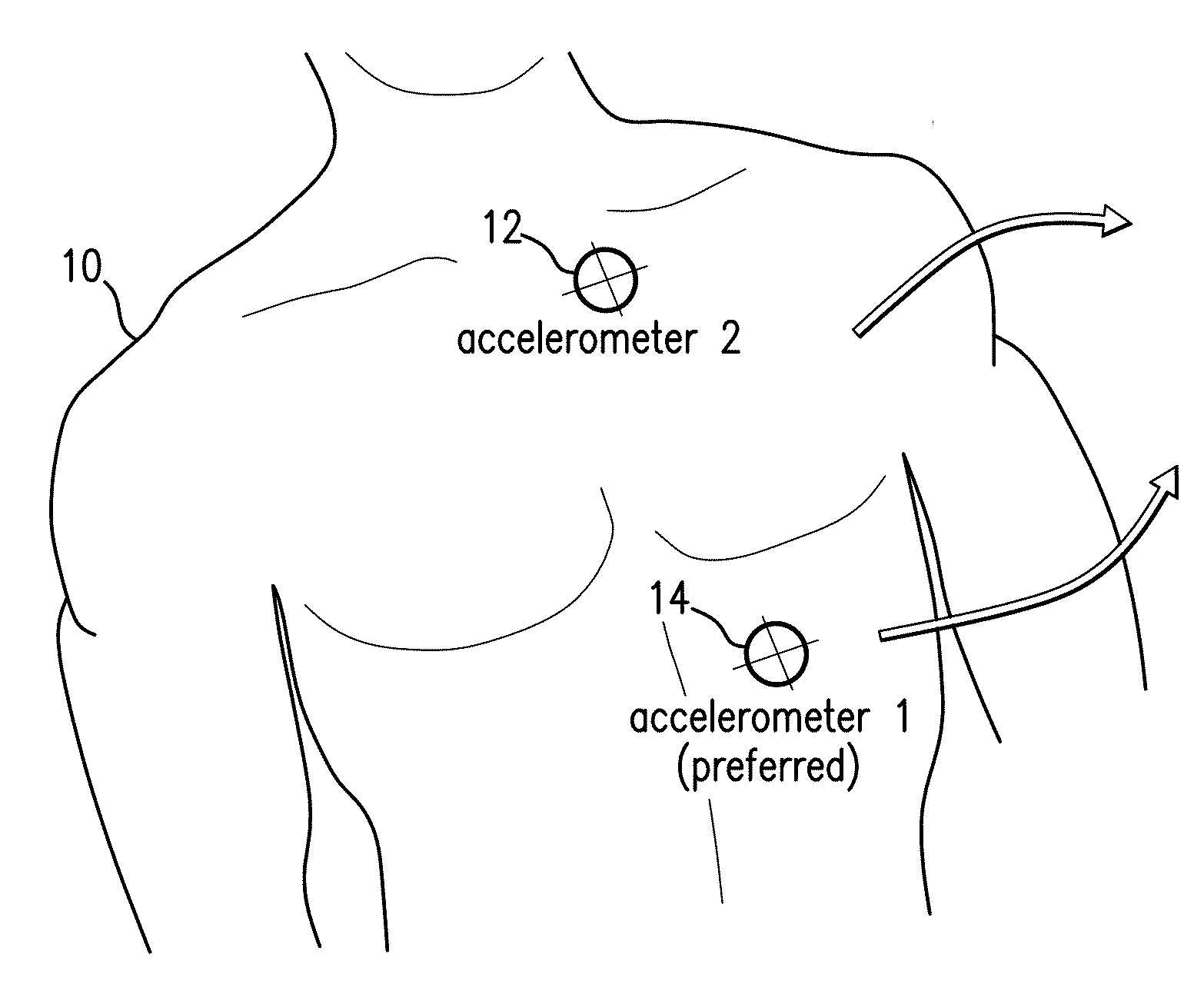
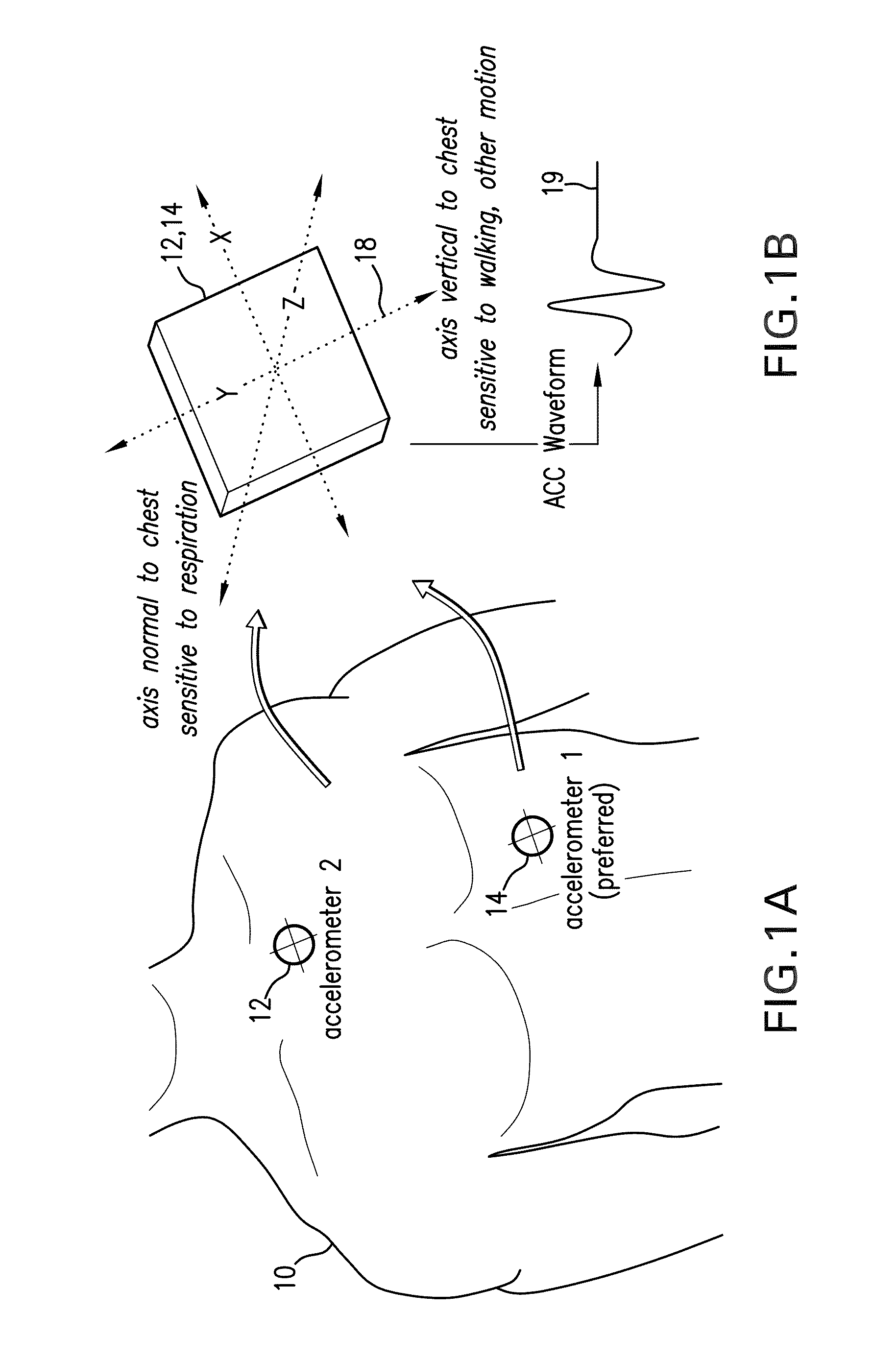
[0074]Referring to FIGS. 1A and 1B, a pair of accelerometers 12, 14 attach, respectively, to the chest and abdomen of a patient 10 to predict RR through the patient's torso movement and an algorithm based on adaptive filtering. Each accelerometer 12, 14 simultaneously measures acceleration (e.g. motion) along x, y, and z axes of a local coordinate system 18. As shown in FIG. 1B, the accelerometers 12, 14 are preferably aligned so the z axis points into the patient's torso. Within each accelerometer 12, 14 is an internal analog-to-digital converter that generates a digital ACC waveform 19 corresponding to each axis. Waveforms are sent as a stream of digital data to a wrist-worn transceiver (shown, for example, in FIGS. 27A, B, and 28) where they are processed using an adaptive filtering algorithm described in detail below to determine the patient's RR. Alternatively, the adaptive filtering algorithm can be performed with a microprocessor mounted proximal to the ac...


PUM


Abstract

The invention provides a multi-sensor system that uses an algorithm based on adaptive filtering to monitor a patient's respiratory rate. The system features a first sensor selected from the following group: i) an impedance pneumography sensor featuring at least two electrodes and a processing circuit configured to measure an impedance pneumography signal; ii) an ECG sensor featuring at least two electrodes and an ECG processing circuit configured to measure an ECG signal; and iii) a PPG sensor featuring a light source, photodetector, and PPG processing circuit configured to measure a PPG signal. Each of these sensors measures a time-dependent signal which is sensitive to respiratory rate and, during operation, is processed to determine an initial respiratory rate value. An adaptive digital filter is determined from the initial respiratory rate. The system features a second sensor (e.g. a digital 3-axis accelerometer) that attaches to the patient's torso and measures an ACC signal indicating movement of the chest or abdomen that is also sensitive to respiratory rate. This second signal is processed with the adaptive filter to determine a final value for respiratory rate.

Description

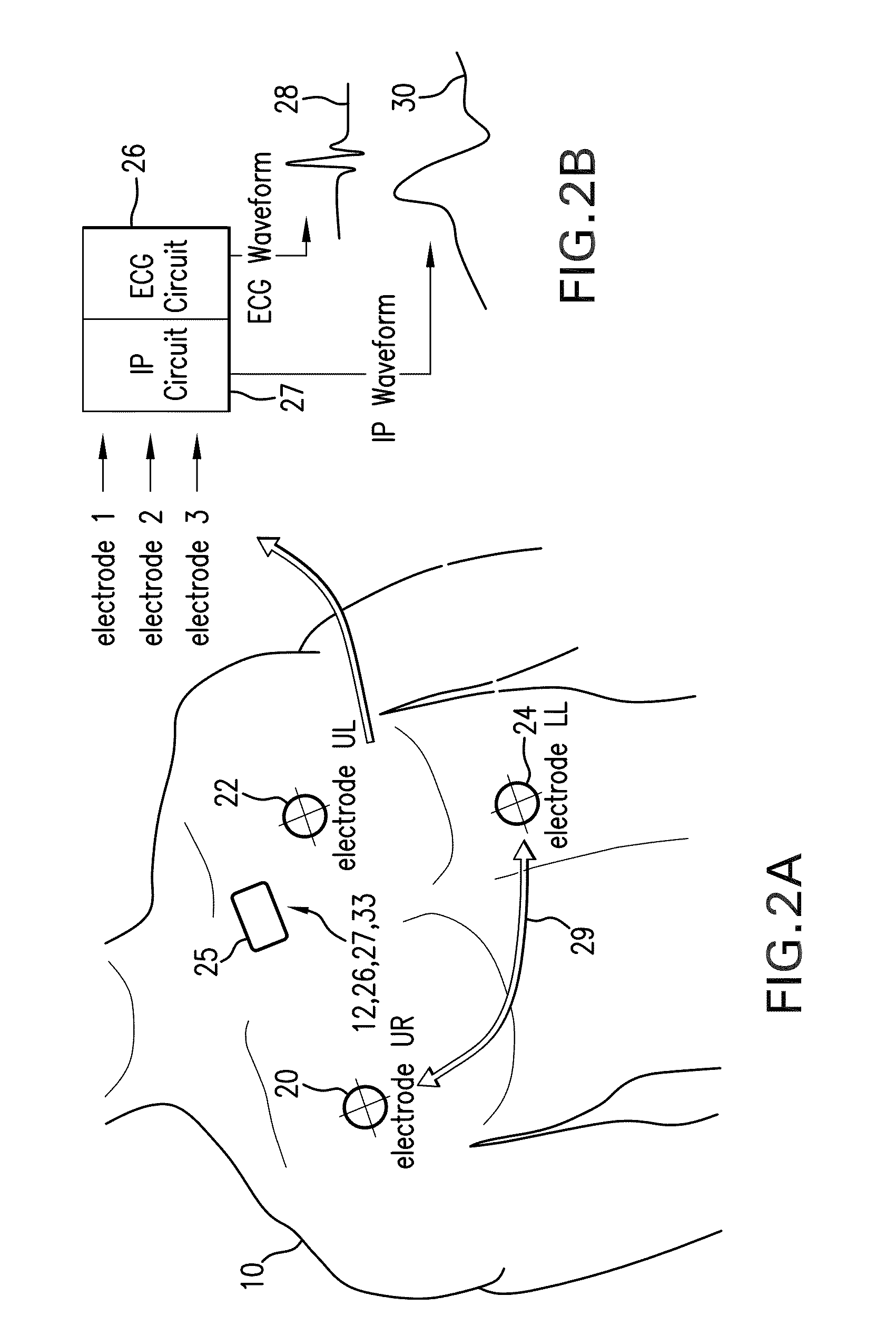
CROSS REFERENCES TO RELATED APPLICATIONS[0001]Not ApplicableSTATEMENT REGARDING FEDERALLY SPONSORED RESEARCH OR DEVELOPMENT[0002]Not ApplicableBACKGROUND OF THE INVENTION[0003]1. Field of the Invention[0004]The present invention relates to medical devices for monitoring vital signs, e.g., respiration rate.[0005]2. Description of the Related Art[0006]Respiration rate (RR) is a vital sign typically measured in the hospital using either an indirect electrode-based technique called ‘impedance pneumography’ (IP), a direct optical technique called ‘end-tidal CO2’ (et-CO2), or simply through manual counting of breaths by a medical professional. IP is typically used in lower-acuity areas of the hospital, and uses the same electrodes deployed in a conventional ‘Einthoven's triangle’ configuration for measuring heart rate (HR) from an electrocardiogram (ECG). One of the electrodes supplies a low-amperage (˜4 mA) current that is typically modulated at a high frequency (˜50-100 kHz). Current pa...

Claims


Application Information

Patent Timeline
Patent Type & Authority Applications(United States)
IPC IPC(8): A61B5/0205A61B5/08
CPCA61B5/0002A61B5/6826A61B5/02416A61B5/0402A61B5/0535A61B5/08A61B5/0809A61B5/0816A61B5/1116A61B5/1118A61B5/113A61B5/681A61B5/721A61B2562/0219A61B5/7239A61B5/6823A61B5/6824A61B5/0205A61B5/746A61B5/318A61B5/33
Inventor BANET, MATTMCCOMBIE, DEVINDHILLON, MARSHAL
Owner SOTERA WIRELESS
Learn More