Liquid leakage prevention device and heat dissipation system
A heat dissipation system and anti-leakage technology, which is applied in the direction of cooling/ventilation/heating transformation, electrical components, electrical equipment structural parts, etc., can solve problems such as potential safety hazards, and achieve the effect of avoiding safety accidents
- Summary
- Abstract
- Description
- Claims
- Application Information
AI Technical Summary
Problems solved by technology
Method used
Image

Examples
Embodiment 1
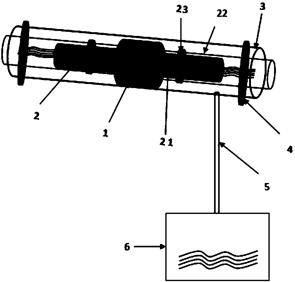
[0030] refer to figure 1 As shown, the anti-leakage device of the present invention includes a heat dissipation device and a sleeve 3, wherein the heat dissipation device includes an adapter 1 and a circulating liquid pipe 2, and a section of circulating liquid pipe 2 is respectively provided on both sides of the adapter 1 for realizing circulation The connection of the liquid pipes 2 constitutes a link in the entire cooling system.
[0031] The circulating liquid pipe 2 includes a metal pipe 21 inserted into the adapter and a plastic pipe 22 that abuts on the adapter 1 and communicates with the metal pipe 21 and is sheathed together to realize the circulation of the circulating liquid. The metal pipe 21 and the plastic pipe 22 They are fixed by the first clip 23. In the working state, the circulating fluid flows through the circulating fluid pipe 2, flows through the adapter and enters the circulating fluid pipe again, and the joint between the adapter 1 and the circulating ...
Embodiment 2
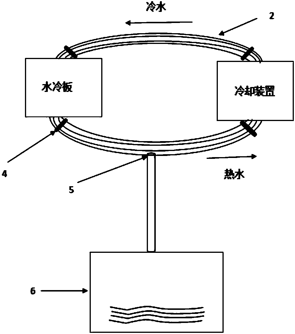
[0042] refer to Figure 5 with Image 6As shown, it is the anti-leakage device and heat dissipation system of this embodiment, which is basically the same as the first embodiment. The anti-leakage device includes a heat dissipation device, a sleeve 3 and a second clamp 4, wherein the heat dissipation device includes a heat dissipation device It includes a liquid cold plate and a cooling device connected through a circulating liquid pipe 2, and the circulating liquid pipe 2 is connected through an adapter 1. The circulating liquid pipe 2 includes a metal pipe 21 , a plastic pipe 22 and a first clip 23 . The only difference is that, in this embodiment, no diversion holes or guide tubes are provided on the casing 3, but the water-absorbing material 9 is used to absorb the leaking liquid so as to avoid excessive leakage of liquid from accumulating in the casing. corrosion. The water-absorbing material 9 can be filled in the entire sleeve 3 or coated on the inner wall of the sle...
Embodiment approach
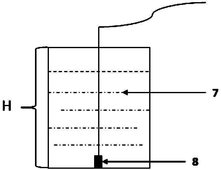
[0044] refer to Figure 7 As shown, it is the third embodiment of the present invention, which is improved on the basis of the first embodiment. The pipe 3 is a ditch-like structure, and the casing 3 is arranged at the bottom of the circulating liquid pipe 2, and is used to drain the leakage at the connection between the circulating liquid pipe and the adapter, and carry it to the receiving container at the bottom of the casing for further recovery or treatment.
[0045] The beneficial effects of the present invention are: different from the situation of the prior art, the present invention provides a liquid leakage prevention device and a heat dissipation system, the liquid leakage prevention device includes an adapter, a circulating liquid pipe connected and fixed through the adapter, and a As for the casing for receiving the leakage, the casing is at least sheathed at the joint between the adapter and the circulating liquid pipe. The invention realizes the separation of wa...
PUM
 Abstract
Description
Claims
Application Information
 - R&D
- Intellectual Property
- Life Sciences
- Materials
- Tech Scout
- Unparalleled Data Quality
- Higher Quality Content
- 60% Fewer Hallucinations
Browse by: Latest US Patents, China's latest patents, Technical Efficacy Thesaurus, Application Domain, Technology Topic, Popular Technical Reports.
© 2025 PatSnap. All rights reserved.Legal|Privacy policy|Modern Slavery Act Transparency Statement|Sitemap|About US| Contact US: help@patsnap.com