
High-air falling prevention device for spraying detection equipment

A detection equipment and anti-drop technology, which is applied in the field of building water detection, can solve problems affecting work efficiency, drop, waste, etc., and achieve the effects of improving safety, improving stability, and reducing friction

Pending Publication Date: 2019-08-16
深圳市居安建筑科技有限公司
View PDF0 Cites 1 Cited by
  • Summary
  • Abstract
  • Description
  • Claims
  • Application Information

AI Technical Summary

Problems solved by technology

[0004] The current spraying method is obviously more troublesome. On the one hand, it will waste a lot of manpower, which will easily bring fatigue to the staff and affect work efficiency; The situation of falling from a high altitude will bring hidden dangers and unnecessary troubles to the entire water spraying inspection work

Method used


Image

  • High-air falling prevention device for spraying detection equipment
  • High-air falling prevention device for spraying detection equipment
  • High-air falling prevention device for spraying detection equipment

Examples


Embodiment 1

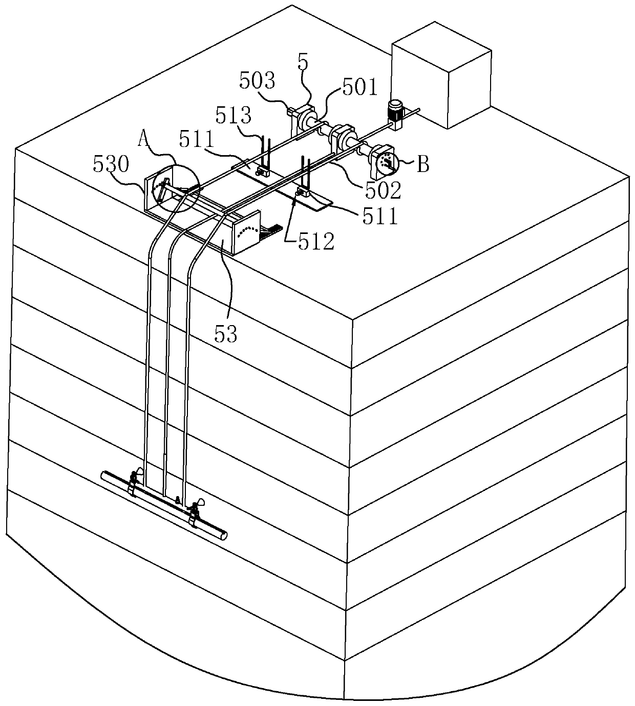
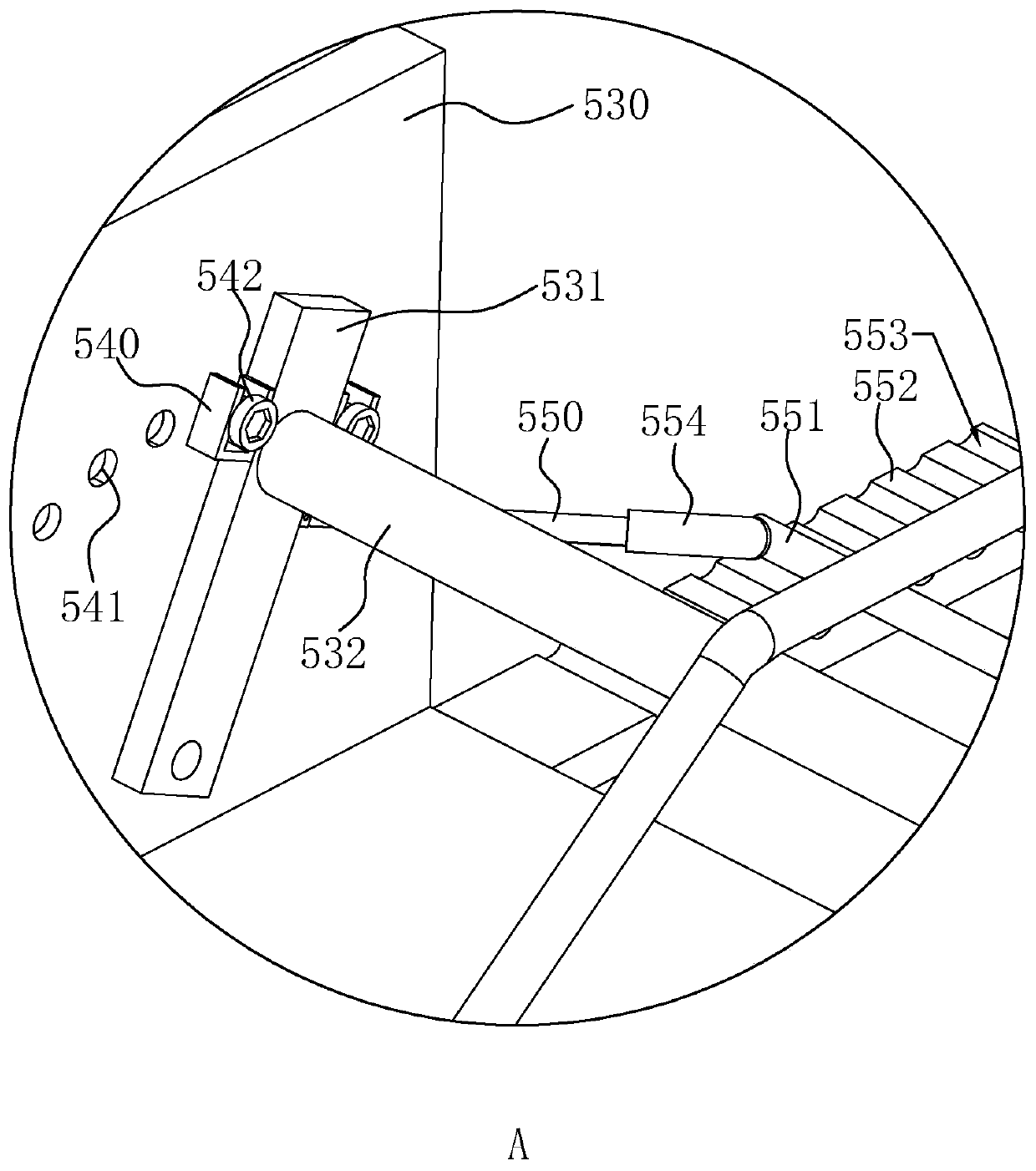
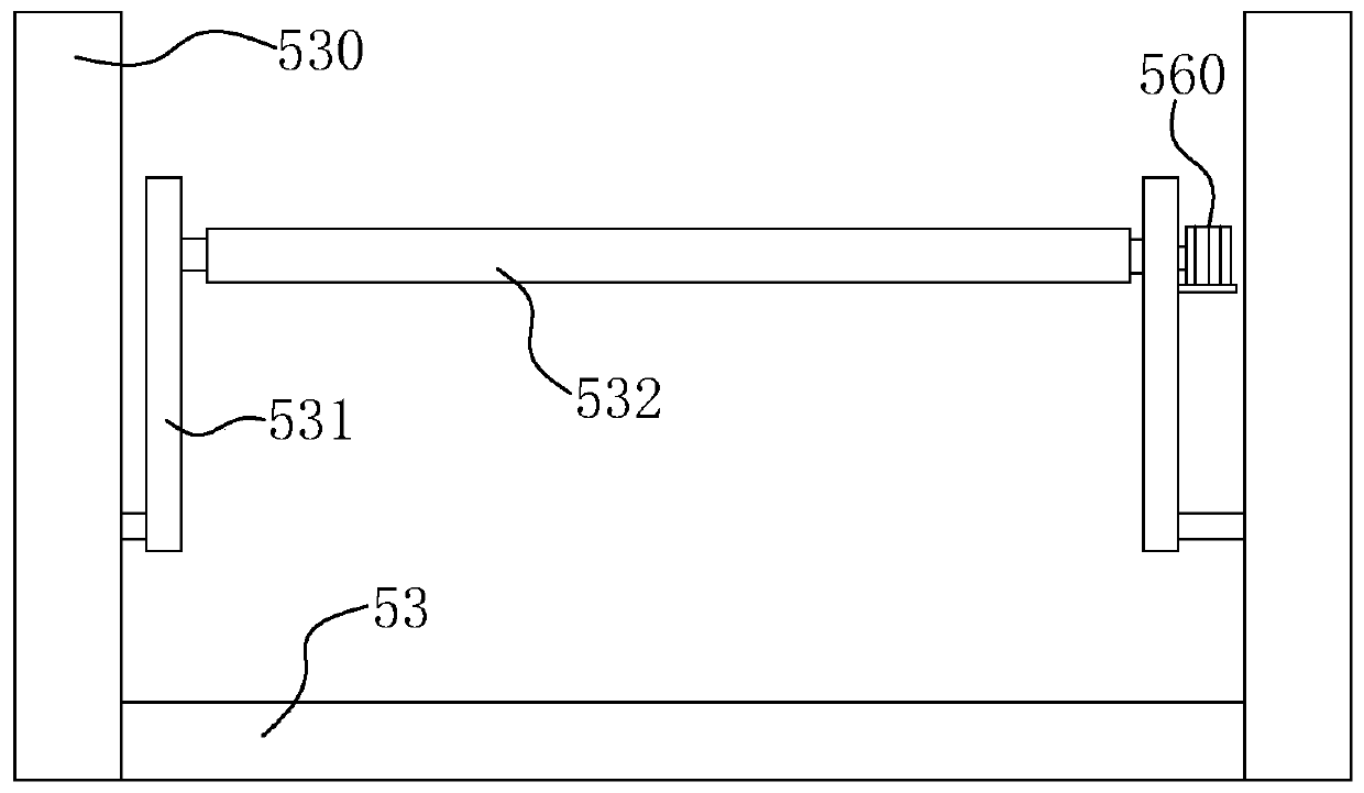
[0038] Example 1: A high-altitude anti-falling device for spray detection equipment, such as figure 1 with figure 2 As shown, a frame 5 is installed on the roof, and a symmetrical winding drum 501 is installed on the frame 5. The winding drums 501 are linearly arranged side by side, and ropes 502 are wound on the winding drums 501. The end of 502 away from the winding drum 501 is connected to the spray assembly. At the same time, a drive assembly is installed on the frame 5. In this embodiment, the drive assembly is a motor 503 installed on the frame 5. The root shaft drives the two winding drums 501 to rotate synchronously, so that the rising and falling of the entire spray assembly can be controlled.

[0039] A correction component is provided on the roof. The correction component can be in contact with the winding rope 502 to correct the rope 502, so that when the rope 502 is wound on the winding drum 501, it can be wound in order and direction, thereby reducing The rope 502 ...

Embodiment 2

[0051] Example 2: Such as Figure 5 As shown, the difference from Embodiment 1 lies in the difference of the correcting component. In this embodiment, the correcting component includes: a backing plate 520 laid at a predetermined position on the roof, and a moving block is slidably connected to the backing plate 520, The sliding direction of the moving block is approximately the same as the extension direction of the winding drum 501, and a U-shaped plate 521 is vertically fixed on the moving block. In addition, a second power part is installed on the backing plate 520, and the second power part can be turned on The moving block is driven to drive the U-shaped plate 521 to slide, and the U-shaped plate 521 can swing the rope 502 during the moving process, and can also cause the rope 502 to be wound on the winding drum 501 in a predetermined order and direction.

[0052] The second power element in this embodiment is a hydraulic cylinder 522 installed on the backing plate 520. Whe...


PUM


Abstract

The invention relates to a high-air falling prevention device for spraying detection equipment, and belongs to the technical field of construction water spraying detection. According to the technicalscheme, the high-air falling prevention device comprises a rack, winding drums, a rope and a driving component, wherein the rack is arranged on a roof, the winding drums are symmetrically arranged onthe rack, one end of the rope is wound on the winding drums and the other end of the rope is connected to a spraying component, the driving component is arranged on the rack and is used for driving the winding drums to rotate, and a deviation correcting component is further arranged on the roof and is used for carrying out deviation correcting on the rope to enable the rope to be wound on the winding drums in a preset direction. During using the high-air falling prevention device, when water spraying detection is carried out, the safety of the whole spraying detection equipment can be improved, the labor amount of workers is reduced, and unnecessary risks and troubles are reduced.

Description

Technical field [0001] The invention relates to the technical field of building water spray detection, in particular to a high-altitude fall prevention device for spray detection equipment. Background technique [0002] With the rapid development of my country’s urbanization, modern residential, office, and commercial-intensive high-rise and super high-rise buildings are rapidly expanding. Strong storms and rains often occur in my country’s coastal areas, lake areas, and flat and plains, resulting in leakage of building exterior walls, doors and windows The problem is obvious. [0003] At present, for the exterior walls and exterior windows of some buildings, water permeability testing is required. When the existing spray testing equipment performs water spray testing on the exterior wall of the building, it is generally used to manually hold the spray pipe on the exterior wall of the building. Or spray from the outer window, or hang the spray assembly at a predetermined position t...

Claims


Application Information

Patent Timeline
Patent Type & Authority Applications(China)
IPC IPC(8): B65H75/38
CPCB65H75/38
Inventor 黄红徐利洪张庭亮刘军
Owner 深圳市居安建筑科技有限公司
Learn More