
Steel angel set, steel channel set for splicing of timber formwork, and construction method

A construction method and wood formwork technology, which is applied in the field of channel steel sets for splicing wood formwork and angle steel sets for splicing wood formwork, and can solve the problems of easily damaged formwork, reduced turnover rate of formwork, and increased cost

Inactive Publication Date: 2019-08-16
CHINA RAILWAY NO 2 ENG GRP CO LTD +1
View PDF3 Cites 3 Cited by
  • Summary
  • Abstract
  • Description
  • Claims
  • Application Information

AI Technical Summary

Problems solved by technology

[0003] The purpose of the present invention is to overcome the troublesome construction of the conventional wooden formwork existing in the prior art, and it is difficult to ensure the flatness of the splicing part, which makes the formwork very easy to be damaged when the formwork is removed, resulting in a decrease in the turnover rate of the formwork and an increase in cost. Provide an angle steel kit for splicing wood formwork

Method used


Image

  • Steel angel set, steel channel set for splicing of timber formwork, and construction method
  • Steel angel set, steel channel set for splicing of timber formwork, and construction method
  • Steel angel set, steel channel set for splicing of timber formwork, and construction method

Examples


Embodiment 1

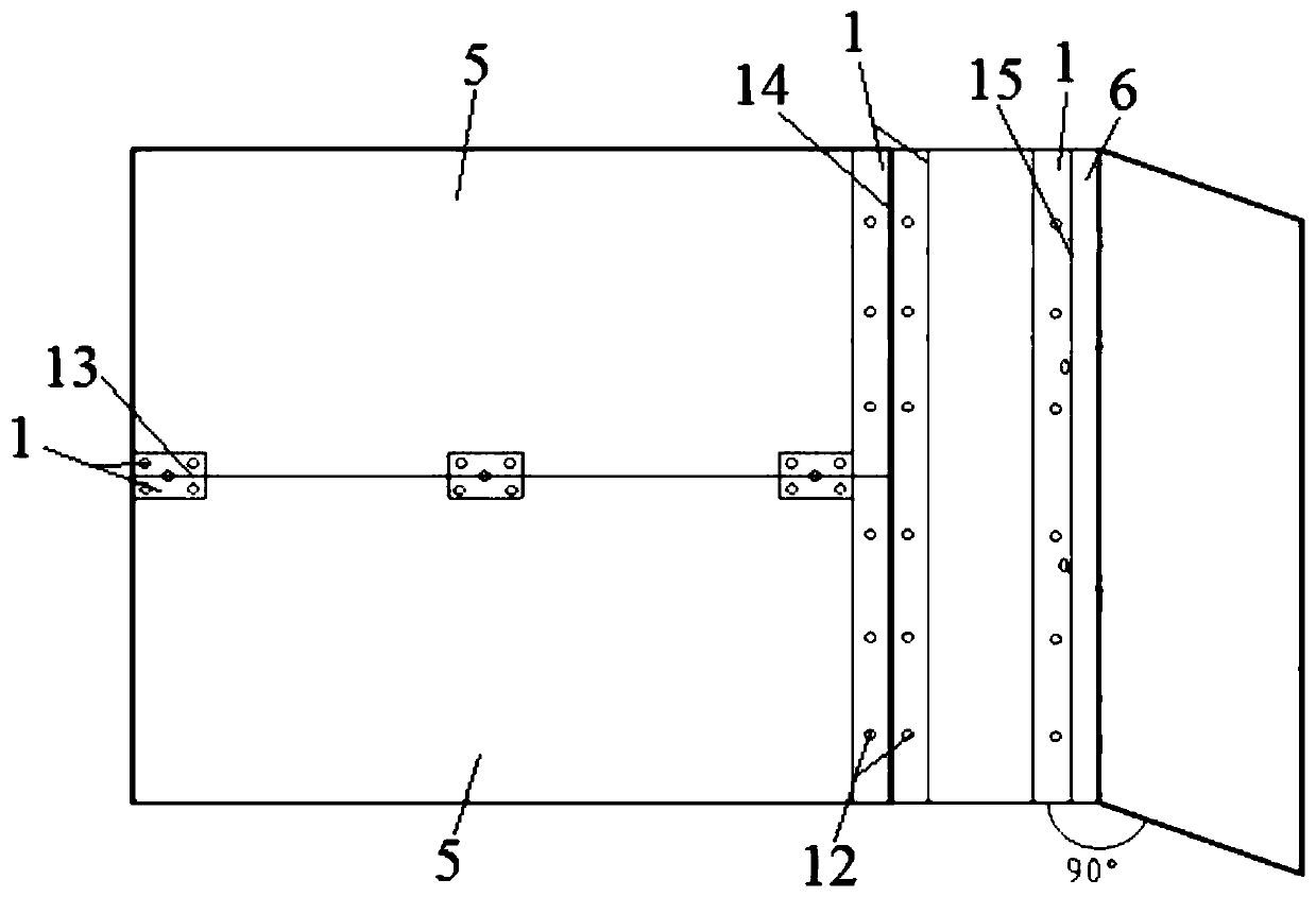
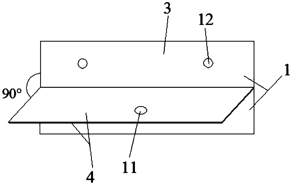
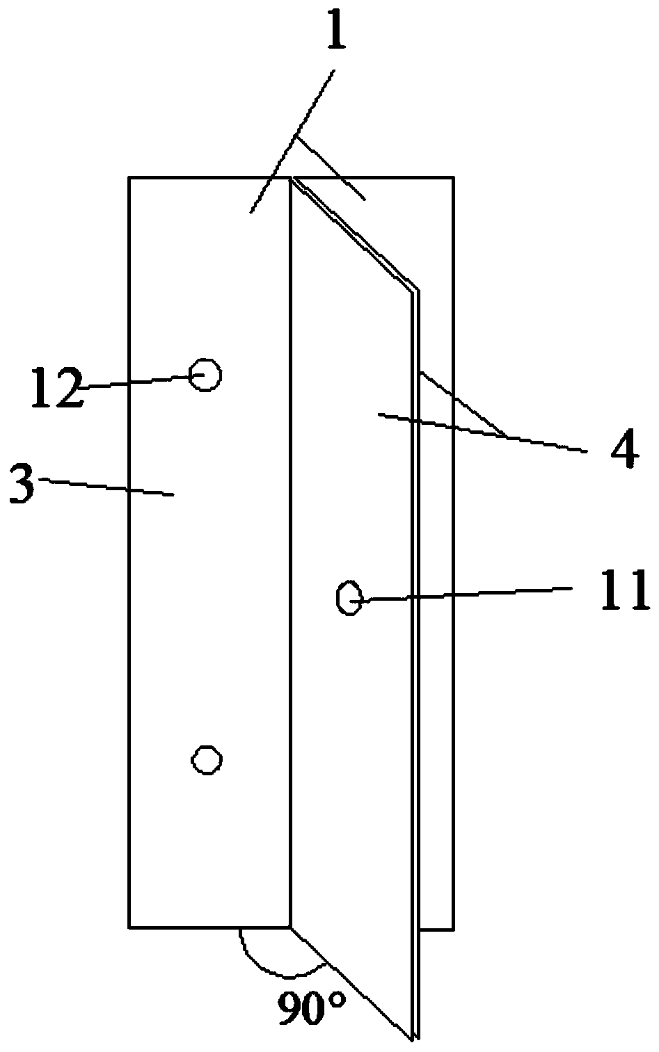
[0041] Such as figure 1 and figure 2 as shown, figure 2 It is a structural schematic diagram of the horizontal splicing 13 of the angle steel 1 set, a wooden formwork 5 splicing angle steel 1 set, including two angle steels 1 and several steel pins 2, and each angle steel 1 includes a first side 3 and a second side perpendicular to each other. Two sides 4, the first sides 3 of the two angle steels 1 are respectively used to connect two wooden templates 5, the second sides 4 of the two angle steels 1 are fixedly connected to each other by a plurality of steel pins 2 and spliced ​​together Form a T-shaped member.

[0042] A second through hole 12 is provided on the first side 3, and the second through hole 12 is used for bolt connection.

[0043] Such as image 3 As shown, the structural schematic diagram of the vertical splicing 14, the splicing principle is the same as the horizontal splicing 13, but the placement position of the wooden formwork 5 is different.

[0044]...

Embodiment 2

[0048] Such as figure 1 and Figure 7 as shown, Figure 7 It is a structural schematic diagram of the vertical splicing 15 of the channel steel 6 sets, a channel steel set for wooden template splicing, including an angle steel 1 and a channel steel 6, and the angle steel 1 includes a first side 3 and a second side 4 perpendicular to each other, The channel steel 6 includes a bottom end and a first end 7 and a second end 8 vertically connected to both sides of the bottom end, the first side 3 of the angle steel 1 and the first end 7 of the channel steel 6 are respectively used for connecting When two wooden templates 5 are vertically spliced ​​15, the second side 4 of the angle steel 1 and the second end 8 of the channel steel 6 are spliced ​​with each other, and fixed and spliced ​​with each other by a plurality of steel pins 2 to form an F-shaped member.

[0049] Steel pin 2 in embodiment 2 is identical in structure and function with steel pin 2 in embodiment 1;

[0050] S...

Embodiment 3

[0054] A kind of wooden template 5 splicing construction method, following steps:

[0055] The first step is to customize angle steel 1 and channel steel 6, customize angle steel 1 and channel steel 6 of different specifications according to the construction area, and make the first through hole 11 and the second through hole 12;

[0056] The second step is to customize the steel pins 2, determine the quantity of the steel pins 2 according to the quantity of the first through holes 11, and make the same number of steel pins 2;

[0057] The third step, flatness inspection, check the flatness of angle steel 1 and channel steel 6, and check whether the size and bending angle of angle steel 1 and channel steel 6 meet the requirements;

[0058] The fourth step, check the hole position, check the opening positions of the angle steel 1 and the channel steel 6, check whether the opening positions are aligned, and ensure the splicing quality of two identical angle steel 1, and the angl...


PUM


Abstract

The invention relates to a device for splicing of a timber formwork, in particular to a steel angle set, steel channel set for splicing of the timber formwork and a construction method. A plurality ofsteel angles and steel pins are arranged, at least one steel angle is arranged on one timber formwork, each the steel angel comprises a first edge and a second edge which are perpendicular to each other, the first edges are fixed to the timber formwork, and two steel angles are fixed through one steel pin; the steel angle set further comprises steel channels, each the steel channel comprises a first end and a second end which are parallel to each other, the first ends are fixed to the timber formwork, and when splicing, the steel angles and the steel channels are fixedly connected through thesteel pins. Splicing of timber formwork in the middle part is completed through combination fixing of the steel angles and the steel channels, and splicing of timber formwork the internal corner partof the construction surface is completed through combination fixing of the steel angles and the steel channels; battens are replaced by the steel angles and the steel channels, the problem that the flatness of splicing parts is difficult to guarantee is solved, and the problem that the formwork is extremely prone to being destroyed when form stripping, and consequently the turnover rate of the formwork is lowered, and the cost is increased is solved.

Description

technical field [0001] The invention relates to a splicing tool for wood formwork, in particular to an angle steel set for splicing wood formwork, a channel steel set for splicing wood formwork, and a construction method for splicing wood formwork. Background technique [0002] At present, the commonly used splicing method of wooden formwork is to nail wooden squares at the joint of two wooden formworks. This method of splicing construction is inefficient, and it is difficult to ensure the flatness of the splicing point, and it is difficult to control the splicing gap, especially the splicing quality of internal corners is often poor. This splicing method makes construction troublesome and easily damages the formwork during formwork removal, resulting in a reduction in the turnover rate of the formwork, and at the same time, there will be a certain loss of wooden squares when used; this splicing method requires the use of more wooden squares, and the cost is higher. Content...

Claims


Application Information

Patent Timeline
Patent Type & Authority Applications(China)
IPC IPC(8): E04G17/00E04G17/02
CPCE04G17/001E04G17/02
Inventor 邓伟罗蛑孙旭军张华谢进白敏杰赵清明梁尤军宋旭明
Owner CHINA RAILWAY NO 2 ENG GRP CO LTD
Learn More