Plasma etching method

a technology of etching and plasma, applied in the direction of basic electric elements, electrical equipment, electric discharge tubes, etc., can solve the problems of enlarging the hole diameter or line width beyond the designed value, bowing of etched shapes, errors in target films,

Active Publication Date: 2014-12-25
TOKYO ELECTRON LTD
View PDF3 Cites 312 Cited by
  • Summary
  • Abstract
  • Description
  • Claims
  • Application Information

AI Technical Summary

Benefits of technology

[0007]In view of the above, the present invention provides a plasma etching method capable of satisfactorily etching an amorphous carbon layer without enlarging etched portions thereof.

Problems solved by technology

However, when hole patterns or line patterns are formed by etching an amorphous carbon layer with a plasma of gas, such etching is performed in both vertical and horizontal directions, thereby making errors such as bowings in etched shapes or enlarging hole diameters or line widths beyond the designed values.
If such errors are made in a specific film, errors are also made in a target film to be etched when the etching is performed on the target film by using the specific film as a mask.
However, it may be difficult to use the COS gas due to residues made from the COS gas, and the like.

Method used


Image

  • Plasma etching method
  • Plasma etching method
  • Plasma etching method

Examples


Embodiment Construction

[0019]An embodiment of the present invention will now be described in detail with reference to the accompanying drawings which form a part hereof.

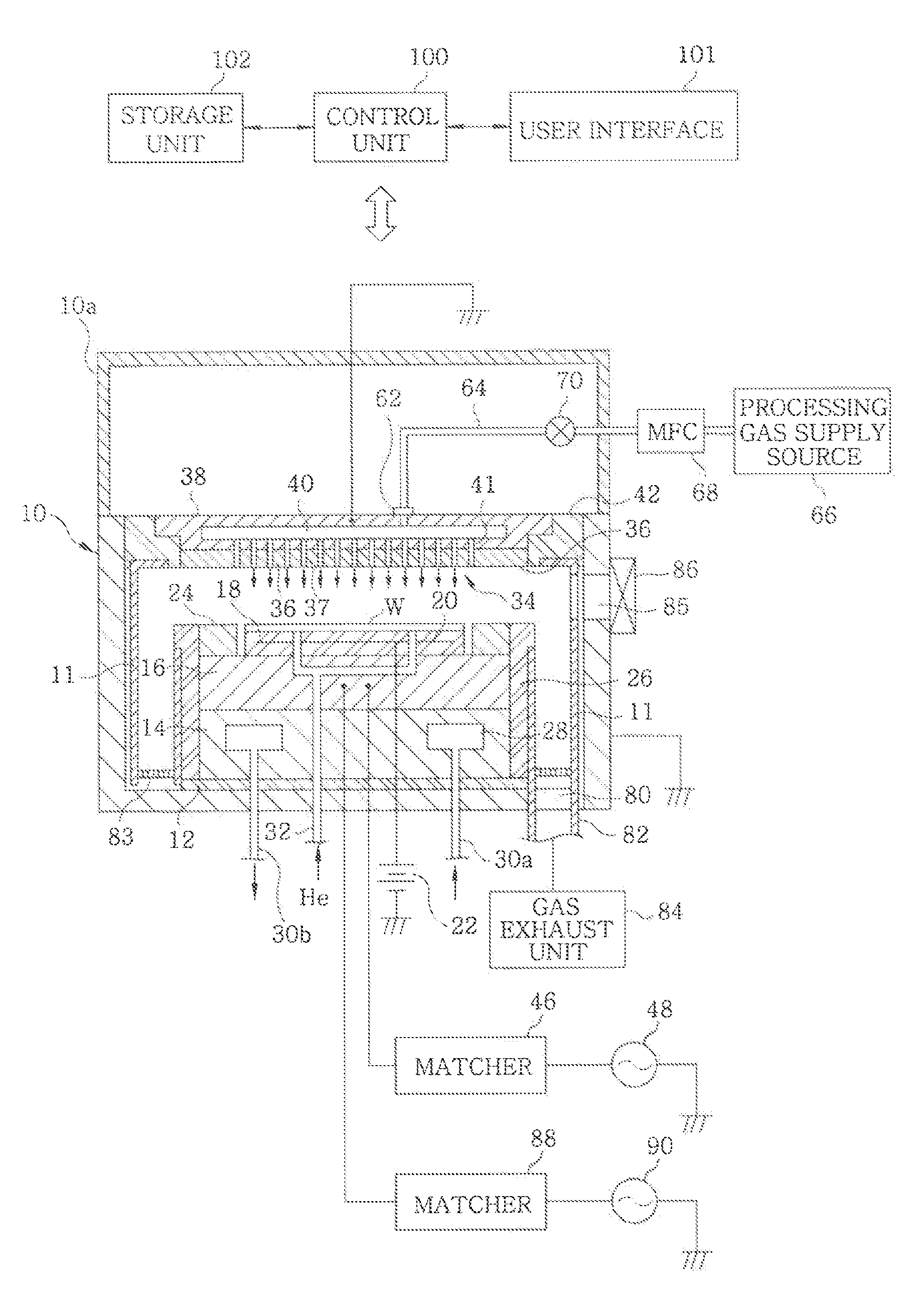
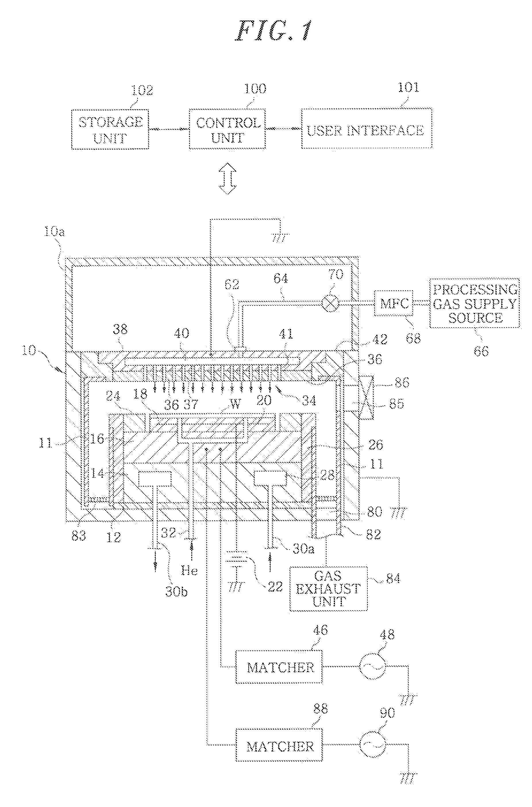
[0020]FIG. 1 is a schematic cross sectional view showing an example of a plasma etching apparatus for performing a plasma etching method in accordance with an embodiment of the present invention.

[0021]The plasma etching apparatus is a capacitively coupled parallel plate type etching apparatus and includes a substantially cylindrical chamber (processing vessel) 10 made of, e.g., aluminum whose surface is anodically oxidized. The chamber 10 is frame-grounded.

[0022]At a bottom portion of the chamber 10, a substantially cylindrical susceptor support 14 is provided via an insulating plate 12 made of, e.g., ceramic or the like. Further, a susceptor 16 made of, e.g., aluminum is provided on the susceptor support 14. The susceptor 16 serves as a lower electrode, and a target substrate, e.g., a semiconductor wafer W, to be processed is mounted on t...


PUM

PropertyMeasurementUnit
residence timeaaaaaaaaaa
pressureaaaaaaaaaa
widthaaaaaaaaaa

Abstract

In a plasma etching method of performing a plasma etching on an amorphous carbon layer of a substrate to be processed by using an inorganic film as a mask, the substrate being mounted in a processing chamber, the plasma etching on the amorphous carbon layer is performed by using O2 gas as a processing gas and the O2 gas to flow in the processing chamber such that a residence time of the O2 gas becomes 0.37 msec or less. The amorphous carbon layer is used as an etching mask of an etching target film formed on the substrate. The plasma etching is performed by using the O2 gas only.

Description

CROSS-REFERENCE TO RELATED APPLICATIONS[0001]This application is a Continuation-In-Part of and is based upon and claims the benefit of priority from co-pending U.S. application Ser. No. 12 / 861,270, filed Aug. 23, 2010, and also claims the benefit of priority from U.S. provisional application Ser. No. 61 / 242,594, filed Sep. 15, 2009. The present application is further based upon and claims the benefit of priority from Japanese Patent Application No. 2009-196431, filed Aug. 27, 2009. The entire contents of foregoing applications are incorporated herein by reference.FIELD OF THE INVENTION[0002]The present invention relates to a plasma etching method for performing a plasma etching on an amorphous carbon layer.BACKGROUND OF THE INVENTION[0003]In the manufacturing process of a semiconductor device, it is required to perform an etching so as to form hole patterns or line patterns with a high aspect ratio in response to the demand for the scaling-down of a design rule. There has been discl...

Claims


Application Information

Patent Timeline
Patent Type & Authority Applications(United States)
IPC IPC(8): H01L21/3065H01L21/308
CPCH01L21/308H01L21/3065H01L21/31138H01J37/32449H01L21/31122H01L21/31144
Inventor KOIWA, KOUSUKE
Owner TOKYO ELECTRON LTD
Why Eureka
Try Eureka