Method for manufacturing susceptor

a manufacturing method and susceptor technology, applied in the direction of adhesive processes, application, bandages, etc., can solve the problems of low yield and reliability, difficult to prevent the wafer from being and the wafer to be stuck on the susceptor

Active Publication Date: 2010-07-01
NUFLARE TECH INC
View PDF5 Cites 330 Cited by
  • Summary
  • Abstract
  • Description
  • Claims
  • Application Information

AI Technical Summary

Problems solved by technology

However, when a wafer is heated and a process gas is supplied thereto from above as described above, a coating is also formed on members other than on the wafer, which causes the wafer to be stuck on a susceptor.
Then, the wafer fractures and particles are produced therefrom, resulting in low yield and reliability.
However, it is difficult to prevent the wafer from being stuck on the susceptor by only the embossing work because rough surface portions will be completely buried due to thick film growth as thick as 100 μm.
Accordingly, it will be required to form a highly rough surface; however, there is a problem that it is difficult to finely machine a surface of a rigid material such as SiC and further control the shape thereof to be spherical.

Method used


Image

  • Method for manufacturing susceptor
  • Method for manufacturing susceptor
  • Method for manufacturing susceptor

Examples


Embodiment Construction

[0018]An embodiment according to the present invention will be described below with reference to the accompanying drawings.

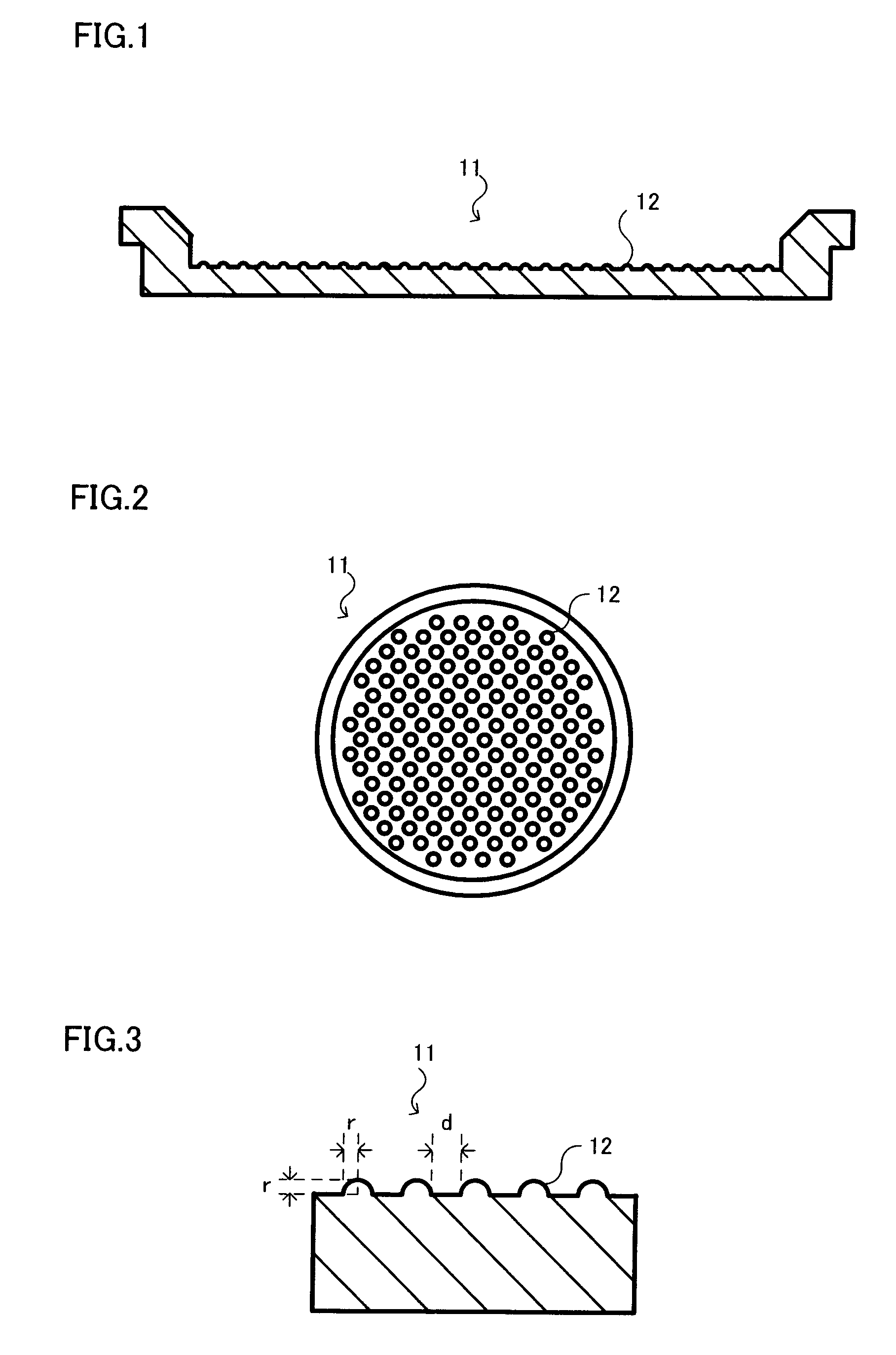
[0019]FIG. 1 illustrates a sectional view of a susceptor formed according to the present embodiment and FIG. 2 illustrates a top view thereof. As illustrated in the figures, convex sections 12 are formed on an entire top face (a wafer placement face) of a susceptor 11 made of SiC. As illustrated in an enlarged view of a cross-sectional portion of the susceptor of FIG. 3, a cross-sectional shape of each of the convex sections is semi-circular and a radius r thereof is, for example, 0.5 mm and an interval d between the convex sections is, for example, 1 mm. A SiC coating (not shown) is formed over the entire top face of the susceptor 11 including the convex sections.

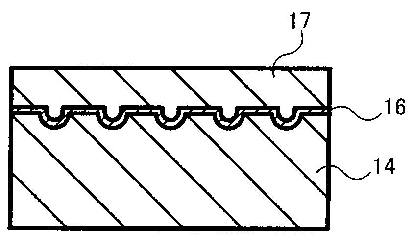
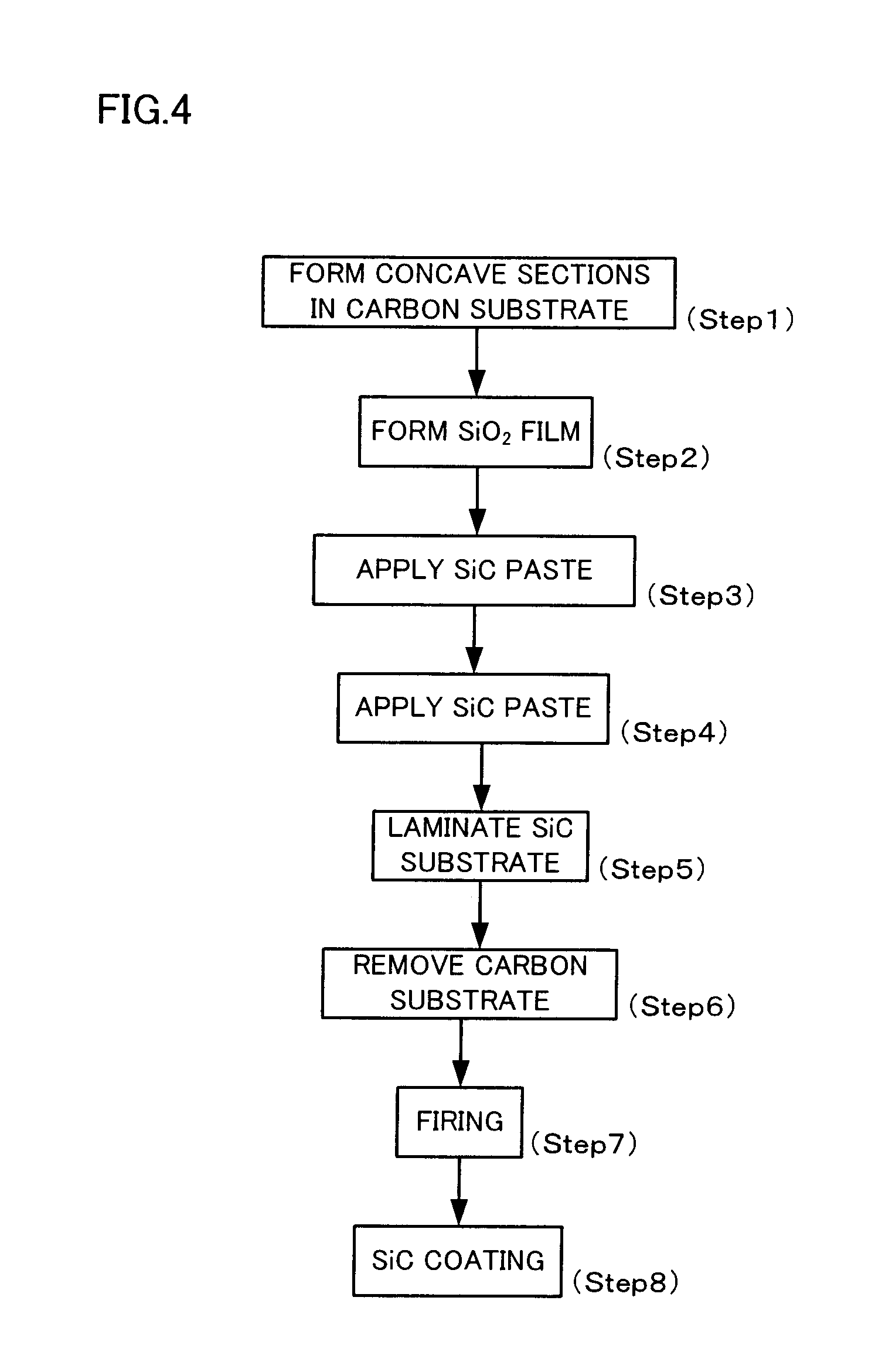
[0020]Such a susceptor is formed as shown in a flowchart of FIG. 4. As illustrated in FIG. 5, a plurality of concave sections 15 having a predetermined diameter and depth are formed at predetermined in...


PUM

PropertyMeasurementUnit
heightaaaaaaaaaa
radiusaaaaaaaaaa
radiusaaaaaaaaaa

Abstract

A method for manufacturing a susceptor includes: forming a concave pattern in a surface of a substrate to be processed; applying a SiC paste containing a SiC powder and a sintering agent to the surface of the substrate to be processed to fill the concave pattern to form a SiC coating layer; laminating a SiC substrate on the SiC coating layer; and firing the SiC coating layer to form a SiC layer having at least one convex section on the surface of the SiC substrate.

Description

CROSS-REFERENCE TO RELATED APPLICATION[0001]This application is based upon and claims the benefit of priority from the prior Japanese Patent Application No. 2008-333544 filed on Dec. 26, 2008, the entire contents of which are incorporated herein by reference.BACKGROUND OF THE INVENTION[0002]1. Field of the Invention[0003]The present invention relates to a method for manufacturing a susceptor that holds a semiconductor wafer, for example, used in performing film formation on the semiconductor wafer.[0004]2. Description of the Related Art[0005]Generally, a CVD (Chemical Vapor Deposition) apparatus is used in forming an epitaxial film or the like on a wafer in a semiconductor manufacturing process. In such a CVD apparatus, a wafer is placed on a susceptor made of SiC or the like and a uniform process gas is supplied to the wafer from above while the wafer is being heated and rotated to form an epitaxial film on the wafer, as described, for example, in Japanese Patent Application Laid-O...

Claims


Application Information

Patent Timeline
Patent Type & Authority Applications(United States)
IPC IPC(8): C09J5/02B44C1/22
CPCC23C16/4581C30B25/12H01L21/68757
Inventor ARAI, HIDEKIYAJIMA, MASAYOSHISUZUKI, KUNIHIKO
Owner NUFLARE TECH INC
Why Eureka
Try Eureka