Detachable cloth lampshade and mounting method thereof

An installation method and cloth lampshade technology, applied in the field of detachable cloth lampshade and its installation, can solve the problems of high packaging and transportation costs, no cost savings, and inability to completely disassemble, etc., to achieve simple structure, reduce production and transportation costs, Solve the huge effect of packaging

Inactive Publication Date: 2019-08-16
广州市旭曜科技股份有限公司
View PDF10 Cites 0 Cited by
  • Summary
  • Abstract
  • Description
  • Claims
  • Application Information

AI Technical Summary

Problems solved by technology

[0002] The traditional cloth lampshade is to directly bond the cloth bag to the bracket welded with metal rings and steel wires, but this kind of lampshade cannot be folded or disassembled, and its volume is relatively large, resulting in high packaging and transportation costs in various links. No, in order to solve this problem, people invented a detachable lampshade, but the existing detachable lampshade is also partially detachable and cannot be completely disassembled. save a lot

Method used


Image

  • Detachable cloth lampshade and mounting method thereof
  • Detachable cloth lampshade and mounting method thereof

Examples


Embodiment 1

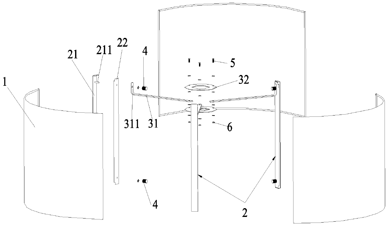
[0021] Such as figure 1 As shown, this embodiment provides a detachable cloth lampshade, including several cloth cover pieces 1, several brackets 2 and supports, the cloth cover pieces 1 are connected by brackets 2 to form a complete cloth cover, and the support members It includes a bent iron 31 and an iron sheet 32 ​​with a central through hole, one end of the bent iron 31 is connected to the iron sheet 32, the other end of the bent iron 32 is connected to the upper end of the bracket 2, the cloth The number of cover sheet 1, support 2, and bent iron 31 are all 3 or 4, and in this embodiment, all are 3.

[0022] Wherein, the bracket 2 includes a first bracket 21 and a second bracket 22, the first bracket 21 is arranged on the outer surface of the joint of the cloth cover sheet 1, and the second bracket 22 is arranged on the outer surface of the joint of the cloth cover sheet 1 On the inner surface, the upper end and the lower end of the first bracket 21 are provided with sc...

Embodiment 2

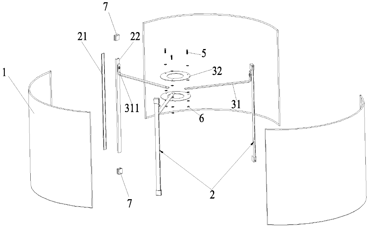
[0028] Such as figure 2 As shown, the difference between this embodiment and Embodiment 1 is that it also includes a buckle 7 for clamping the bracket 2 and the cloth cover sheet 1, and the buckle 7 is clamped at the upper end and the lower end of the bracket 2, and the first A bracket 21 is not provided with a screw rod 211, and the cloth cover sheet 1 and the second bracket 22 are not provided with an opening for the screw rod 211 to pass through, and the bent iron 31 and the second bracket 22 are screwed together. Connection, other structures are the same as in Embodiment 1, and will not be repeated here.

[0029] In the installation method, the difference is: step 2) when installing, place the joint of the cloth cover piece 1 between the first bracket 21 and the second bracket 22, and then pass the buckle at the upper end and the lower end of the joint respectively. 7 Clamping, step 3) During installation, one end of the connecting ear 311 of the bent iron is connected t...


PUM


Abstract

The invention relates to the technical field of lamp lampshades, in particular to a detachable cloth lampshade and a mounting method thereof. The lampshade comprises cloth cover pieces, a support anda supporting part; the cloth cover pieces are connected through the support to form a complete cloth cover, the supporting part comprises curved iron and an iron piece with a center through hole, oneend of the curved iron is connected with the iron piece, the other end of the curved iron is connected with the upper end of the support, during mounting, one end of the curved iron and the iron pieceare mounted and fixed to form the supporting part, through the support, the cloth cover pieces are connected to form the complete cloth cover, the other end of the curved iron is movably connected with the support, and the complete lampshade is obtained. The detachable cloth lampshade is convenient to produce, mounting is convenient, a user can carry out free dismounting and mounting, the giant packaging can be well solved, and production and transport cost is reduced.

Description

technical field [0001] The invention relates to the technical field of lamp shades, in particular to a detachable cloth lamp shade and an installation method thereof. Background technique [0002] The traditional cloth lampshade is to directly bond the cloth bag to the bracket welded by metal rings and steel wires, but this kind of lampshade cannot be folded or disassembled, and its volume is relatively large, resulting in high packaging and transportation costs in various links. No less, in order to solve this problem, people invented a detachable lampshade, but the existing detachable lampshade is also partially detachable and cannot be completely disassembled. The volume after disassembly is still relatively large, and the cost of packaging and transportation is not low Save a lot. Contents of the invention [0003] The invention provides a detachable cloth lampshade which is convenient for production and can be freely disassembled by end users and its installation met...

Claims


Application Information

Patent Timeline
Patent Type & Authority Applications(China)
IPC IPC(8): F21V1/16F21V1/14
CPCF21V1/14F21V1/16
Inventor 张勇
Owner 广州市旭曜科技股份有限公司
Why Eureka
Try Eureka