Balancing weight type hydraulic pumping unit

A technology of counterweight and pumping unit, applied in the field of beamless hydraulic pumping unit and counterweight hydraulic pumping unit, can solve the problems of high energy consumption and poor stability of the frame, and reduce the volume and impact force. , the effect of improving stability

Inactive Publication Date: 2020-03-31
青岛科瑞特传动科技有限公司
View PDF0 Cites 0 Cited by
  • Summary
  • Abstract
  • Description
  • Claims
  • Application Information

AI Technical Summary

Problems solved by technology

[0005] Aiming at the technical problems of high energy consumption and poor frame stability existing in the existing beamless hydraulic pumping unit, the present invention proposes a balance weight hydraulic pumping unit with low energy consumption and high stability

Method used


Image

  • Balancing weight type hydraulic pumping unit
  • Balancing weight type hydraulic pumping unit
  • Balancing weight type hydraulic pumping unit

Examples


Embodiment 1

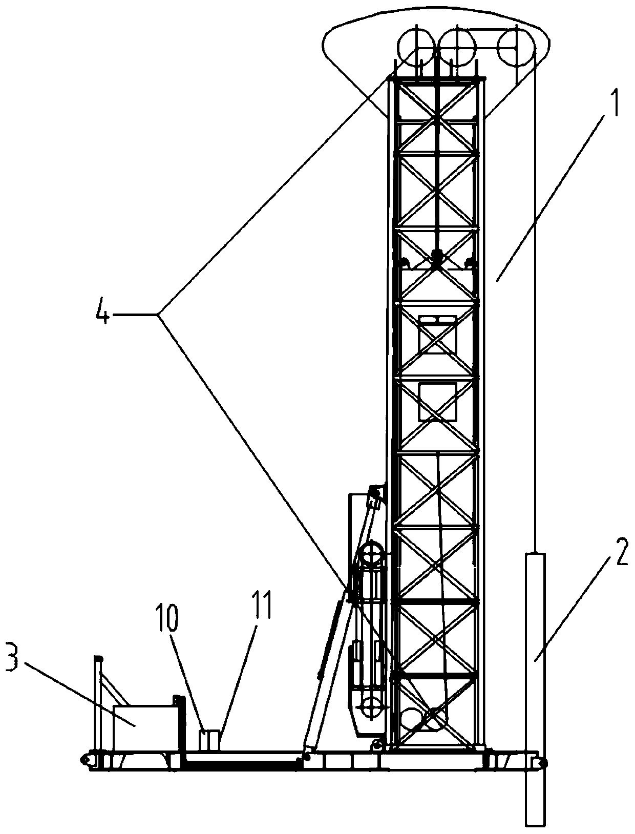
[0039] Such as figure 1 As shown, the counterweight hydraulic pumping unit of the first embodiment of the present invention includes a tower frame 1, a sucker rod 2, a hydraulic constant power power system 3, a stroke amplification system 4, an electronic monitoring and alarm system 10, an electric control system 11, the hydraulic constant power power system includes an oil cylinder to provide power for the sucker rod 1; an electric control system 11 and a monitoring and alarm system 10 are installed on the base below the tower frame, and the top of the tower frame is fixedly equipped with Crane.

[0040] Wherein, the weight of the counterweight is greater than the maximum suspension point load of the sucker rod, and the weight of the counterweight is preferably 1.05 times of the maximum suspension point load of the sucker rod.

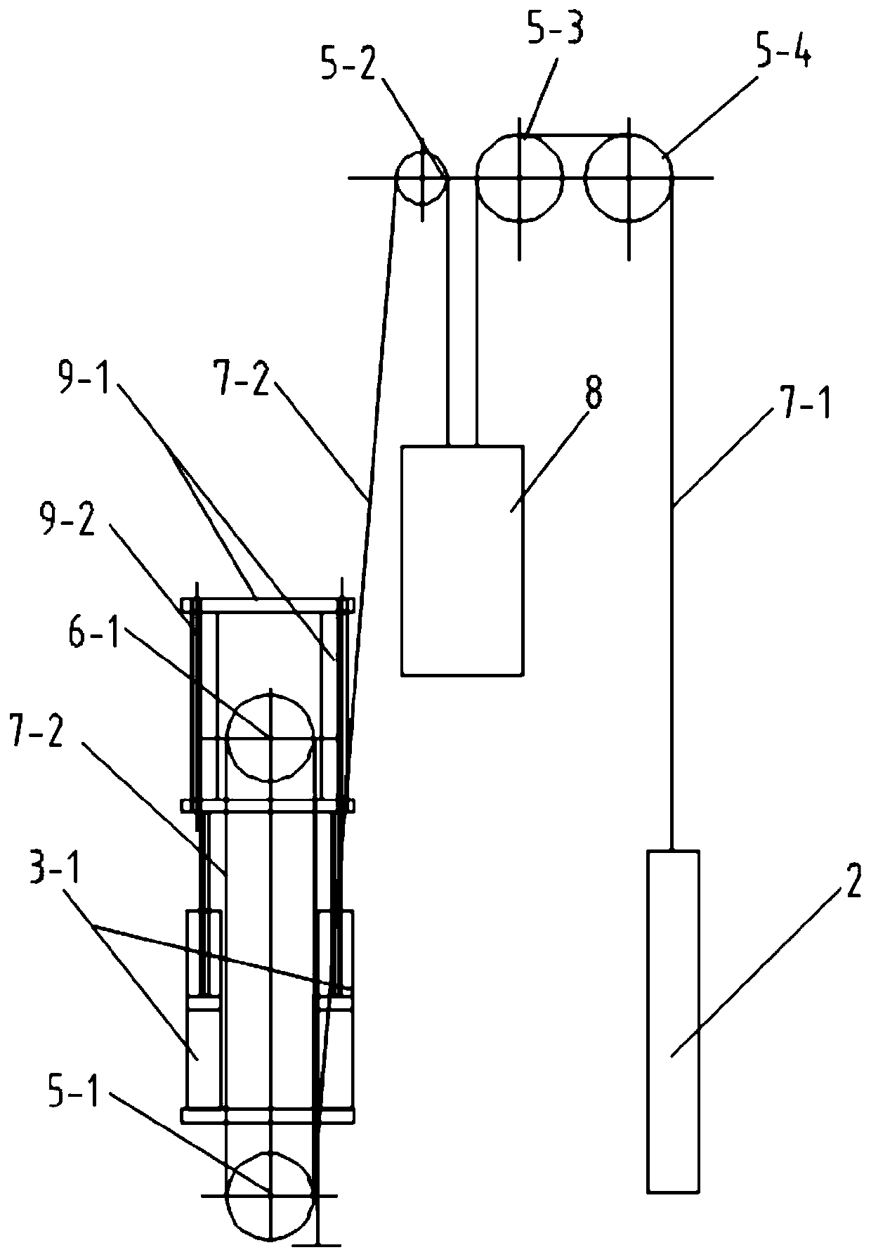
[0041] Such as figure 2 As shown, the stroke amplification system includes a fixed pulley block, a movable pulley block, a lifting device, a count...

Embodiment 2

[0054] The difference between the counterweight hydraulic pumping unit of the second embodiment of the present invention and the embodiment 1 lies in the formation of an amplification system.

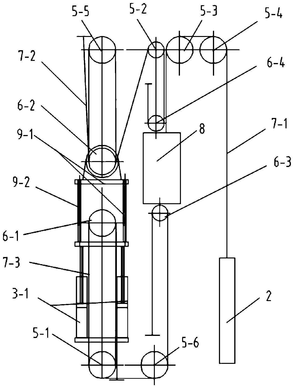
[0055] Such as image 3 As shown, the stroke amplification system includes a fixed pulley block, a movable pulley block, a lifting device, a counterweight and a steel wire rope group; the lifting device is connected to the output end of the oil cylinder, and the steel wire rope group is connected to the lifting device, the fixed pulley block, The counterweight, the movable pulley block, and the end are fixedly connected with the sucker rod, and the short stroke of the oil cylinder is amplified into the long stroke of the sucker rod.

[0056] Specifically: the fixed pulley block has six fixed pulleys, which are respectively the first fixed pulley 5-1, the second fixed pulley 5-2, the third fixed pulley 5-3, the fourth fixed pulley 5-4, and the fifth fixed pulley. Pulley 5-5, the sixth f...


PUM


Abstract

The invention provides a balancing weight type hydraulic pumping unit and solves the problem that an existing walking beam-free hydraulic pumping unit is great in energy consumption and unstable in rack. The balancing weight type hydraulic pumping unit comprises a tower type rack, a sucker rod, a hydraulic constant power dynamical system and a stroke amplifying system. The hydraulic constant powerdynamical system comprises an oil cylinder which provides power to the sucker rod. The stroke amplifying system comprises a fixed pulley block, a movable block, a lifting device, a balancing weight and a steel wire rope group. The lifting device is connected to the output end of the oil cylinder, the steel wire rope group is connected to the lifting device, the fixed pulley block, the balancing weight and the movable block, and the tail end of the steel wire rope group is fixedly connected to the sucker rod. A short stroke of the oil cylinder is amplified to a long stroke of the sucker rod, so that effects of reducing the power of the hydraulic constant power dynamical system and being energy-saving are achieved. The stroke of the balancing weight is amplified by two steel wire ropes to limit the operating track of the balancing weight, so that the stability of the balancing weight is improved, and therefore, the stability of the rack is improved.

Description

technical field [0001] The invention relates to the technical field of oil exploitation equipment, in particular to a counterweight hydraulic oil pumping unit, which is applied to a beamless hydraulic oil pumping unit. Background technique [0002] With the rapid development of oil extraction equipment in China in recent years, and the transformation of pumping units to the direction of long stroke, large load, high efficiency and high intelligence, the beam pumping unit, which is currently the mainstream of domestic and foreign production and sales, is due to its structure Huge, high energy consumption, low intelligence and other defects. [0003] Beamless hydraulic pumping unit is well adapted to oil field pumping operations because of its energy saving, small equipment footprint, and easy realization of large stroke and large load. However, there are still defects such as poor reliability, insignificant energy-saving effect, poor adaptability, and inconvenient maintenanc...

Claims


Application Information

Patent Timeline
Patent Type & Authority Applications(China)
IPC IPC(8): E21B43/00F16F15/28B66D3/08
CPCB66D3/08E21B43/129F16F15/28
Inventor 张玉纲王军伟罗振华魏强
Owner 青岛科瑞特传动科技有限公司
Why Eureka
Try Eureka